Continue to Site

Welcome to our site!

Electro Tech is an online community (with over 170,000 members) who enjoy talking about and building electronic circuits, projects and gadgets. To participate you need to register. Registration is free. Click here to register now.

  • Welcome to our site! Electro Tech is an online community (with over 170,000 members) who enjoy talking about and building electronic circuits, projects and gadgets. To participate you need to register. Registration is free. Click here to register now.

8051 microcontroller

Status
Not open for further replies.
Hi, i made the ckt, it turned out a complete mess. Now its really urgent, i think my pin connections were wrong and something happened to the 8051 i was using, i only heard the microcontroller losing its life, it was all smoky, pls send me the connections somehow to control a 12V,1A DC motor through the controller, i just need to reverse the direction of the motor with the controller, i.e. change the polarity of the supply to the motor using the microcontroller...
Plsss help...:confused::confused::confused::(

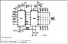
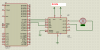
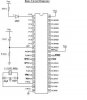
Well, which cct did you use. Can you post or link to the schematic. Did you have diodes across the motor?
 
Actually, there were no diodes in it, i only had in my mind to give a fixed voltage supply to both the microcontoller and the motor used, and it had no diodes.
I had directly connected the motor to the microcontroller. pls help...
 
Actually, there were no diodes in it, i only had in my mind to give a fixed voltage supply to both the microcontoller and the motor used, and it had no diodes.
I had directly connected the motor to the microcontroller. pls help...

You can't connect a motor directly to a microcontroller, particularly an 8051 which has very little current capability.

You need an H-bridge, and the size of it depends on the requirements of the motor.
 
Well i found a circuit rite now, it connects to the microcontroller via a L298 operating at 5 volts, i think it would suffice.
A L298 can be used instead of a h-bridge circuit, i hope so...
 
Well i found a circuit rite now, it connects to the microcontroller via a L298 operating at 5 volts, i think it would suffice.
A L298 can be used instead of a h-bridge circuit, i hope so...

No, that will just provide drive current.
Did you actually look at any of those links I took the time to find for you?
 
Of course i did, and this is one of the circuits i got from there, i communicated there too, nd they sent me this ckt.
 

Attachments

  • untitled.PNG
    untitled.PNG
    19.8 KB · Views: 903
  • powering up.JPG
    powering up.JPG
    52.5 KB · Views: 919
Well i found a circuit rite now, it connects to the microcontroller via a L298 operating at 5 volts, i think it would suffice.
A L298 can be used instead of a h-bridge circuit, i hope so...

Sorry! I read that as UNL2803 for some reason. :eek: Admittedly, I read hastily.

Yes, the L298 is designed for that. There is a circuit diagram on page 6 of the ST data sheet. It shows a motor connected using fast recovery diodes for protection.

The circuit you posted should work, but I would add the diodes. :)

Get the data sheet for yourself, and give it a go. Come back when you have it hooked up, or ...

EDIT: Just so it doesn't confuse you, the L298 is a dual h-bridge, and they are using the other one in each diagram.
 

Attachments

  • ST data sheet p5.gif
    ST data sheet p5.gif
    20.4 KB · Views: 1,634
Last edited:
can i use a 89S52 in place of the 8051, nd use the same program as well, bcoz i read that 8952 is only an advanced version of 8051.
Pls suggest.
 
Download the datasheet and read the specs - but basically it's not a very powerful IC.

The motor current also won't be 1A, it will vary wildly, and during stall or heavy loads will be greatly higher than that.
 
well, i indeed think of connecting the diods between the L298 and the motor, but i dont know which diode, and how to connect it, pls, relate it to the circuit above and send a suitable connecton between the motor and the diode. nd pls suggest which diode to use.
 
i did download a datasheet of the ST electronics, but, i dont know whch ne, i looked it up, and i've got this diagram, just see it nd tell me whether this is the diagram or not.
 

Attachments

  • L298.JPG
    L298.JPG
    39.5 KB · Views: 599
i did download a datasheet of the ST electronics, but, i dont know whch ne, i looked it up, and i've got this diagram, just see it nd tell me whether this is the diagram or not.

Looks like that is the correct data sheet, but that diagram is for stepper motors. It is on page 8, the one you want is on page 6. Look for the same diagram I posted... It is the same thing as what is shown in the circuit you posted, but with the diodes.
 
Should work well. For a diagram, look at the picture I posted from the data sheet. (You DID get yourself a data sheet, didn't you? :D)
Actually schottkys should be used. The fast diode's 1.2V drop, if he is driving the rated current, is actually quite lossy and if the drop in the chip is lower helps very little if it is a synchronous rectifying chip.

Dan
 
Status
Not open for further replies.

Latest threads

New Articles From Microcontroller Tips

Back
Top