Continue to Site

Welcome to our site!

Electro Tech is an online community (with over 170,000 members) who enjoy talking about and building electronic circuits, projects and gadgets. To participate you need to register. Registration is free. Click here to register now.

  • Welcome to our site! Electro Tech is an online community (with over 170,000 members) who enjoy talking about and building electronic circuits, projects and gadgets. To participate you need to register. Registration is free. Click here to register now.

7 segment display programming! pls HELP

Status
Not open for further replies.

Harvester

New Member
Hi! I have a project to do for school about controlling revolution af a stepper motor. And i make this my using a at89c52, instead of a PIC, because if i was using a PIC I wouldnt have enough pins to connect a 7 segment display. On this 7 segment display i want to post the speed of the motor. The problem is that I must make the assembler program for this and i dont know to do it. Can anyone help me with the asm for this?plsssss
I put a attach with the circuit scheme, but instead of that PIC i use an at89c52 + a 7 segments display!
 

Attachments

  • Doc1.ace
    8 KB · Views: 372
  • Doc1.ace
    8 KB · Views: 535
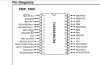
You can control a 7-seg with a 16F84 (18 pin). Even a lot of them. :? Also if you need more pins you can use 16F876, very similar to the other but with 28 pins and, if you want to use them, many added features.

Anyway, you have to write a table where you'll have the translation, from dec, hex or bin (whatever you like most) to 7-seg. Imagine the table like this:

head (it's not a real position, but you should know where (mem position)does the table start)

3F (if you put h'3F' or 0x3F or b'0011 1111' in your port, you'll get a '0' displayed)
06 (you'll get a '1')
5B (...)
4F
66
6D
7D
07 (you'll get a '7')
and so on...

As you know, each LED segment is called by a letter, such 'a' till 'g' (g is the segment in the middle). Ensure you assign the lower port bit to the 'a' segment and you mantain the order until you assign the port bit 7 to the 'g' segment. This way the table above works for those specific values. Otherway, you'll have to guess them, understood?

The procedure is the following:

You have your number to display, ie: 7
Locate yourself at the head of the table.
Then, force the program counter to jump 7 steps.
And ask the micro to return you the value it found there (where he arrived). In the table above, it should return you a h'07'.
Put this value in your port now: A '7' must be displayed.

What if you must control 4 7-seg modules (more than one, anyway)?

Easy! A LED can conmute fron off to on in microseconds and viceversa. All you need is one more pin for enable and disable each 7 seg block.

Once again, the global procedure:
You want to display this number: 531

Enable the first 7 seg module and disable the others.
Do as told above to display a '5'
Disable the first module and enable the second.
Display a '3'
Disable the second and enable the third
Display a '1'

Easy, isn't it? :D
 
First of all, thanx for the explanations. Second, how can I connect a 7segments display to show 3 digits, on a PIC with 18 pins? Third, i already knew that, but i dont know the sintax in assembler, this is MY PROBLEM :cry: , can you help with that ? plss

P.S. I'll give you a beer when you will come in Romania, if you help me! :wink:
 
If you decide to make it with a PIC I can help you because I know its assembly language. Just the answer about the 'how to'. Notice you use only 12 pins ;)

Anyway, I should leave now, cya!
 

Attachments

  • 7seg.GIF
    7seg.GIF
    2.7 KB · Views: 2,567
Man, as long you can control the speed of the motor and display it on a 7 segments display it's OK. I dont know assembler at all and i will take any help from you! Thx again!
 
Can you get a PIC16F876? :?: This one has a very interesting feature for controlling the speed of the motor, I guess, one pin is enough for doing that. It is the PWM (pulse width modulator) which can generates a square wave, but you can adjust the length of the high level vs the low level of each period. So, the longer the high level (and the shorter the low one, the faster the motor works. :idea:

Tell me if I understood your project: You want to move a motor at the speed you set with the microcontroller. After that, you want to measure its speed with the same micro, and then you want to display the value. :?: Or do you want to set the value of the speed, display it and make the motor move at that speed? :roll:

Tell me which PIC you're using. Tell me also, which pins you'll use. Consider the draw I've made for you, because I can ensure it works. I don't know nothing about your motors or about your speed measure, so you'll have to explain it very accurate to me. I can write here, if you want to, the code (usefull for ANY PIC) about the table and making it work.

But, first of all, we should start from a "work flow" diagram. I don't know if this is the correct word. We need a diagram which explains how the microcontroller does its job, with actions and decisions, showing the routins and subroutines. That way I can help you with the code in those parts you are unable to develop. :wink:
 
Have a look at the PIC I'm talking you about:

**broken link removed**

I think it's ok because it costs about 10€
 

Attachments

  • pin16f876.jpg
    pin16f876.jpg
    127.5 KB · Views: 2,680
Here is my project : i have a stepper motor and i want this: i want to be able to control the sense and the speed of him and display the speed on a 7 segment display. In the scheme that i attach before i was doing the sense and speed controll with some switches. I dont have a speed given. I controll this by using those switches. The speed will be a 3(or 4) digits. The motor use also an AC curent. In the file that i have attached before it's the motor that i will use.
Yes, i can get a PIC16F876. The PIC make connection between motor, switches and display. I think you will know better wich pins should I use.
 
You can probably drive four 7-seg displays using only 8 pins. If you're really smart and efficient, you can probably drive four displays using only 4 pins. see MICROCHIP TB029 (Complementary LED drive).
 
Status
Not open for further replies.

Latest threads

New Articles From Microcontroller Tips

Back
Top