Continue to Site

Welcome to our site!

Electro Tech is an online community (with over 170,000 members) who enjoy talking about and building electronic circuits, projects and gadgets. To participate you need to register. Registration is free. Click here to register now.

  • Welcome to our site! Electro Tech is an online community (with over 170,000 members) who enjoy talking about and building electronic circuits, projects and gadgets. To participate you need to register. Registration is free. Click here to register now.

7-Segment-Display (2 Digits) with MOSFETs

Status
Not open for further replies.

sclear

New Member
Hi,

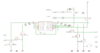
im trying to drive the leds of 7-segments-display (2 digits) with an STM32. I'm using MOSFET transistors to control the segments. I came up with the following circuit (attached).
I got a 3.3V supply and i want to get 10mA on each LED of the display. Can you tell me please if the circuit will work and if my calculations of the resistors are correct?
I calculated the voltage drop of 1V (3.3V - 2V from the LEDs and - 0.3V from the MOSFET). It resulted in 1V / 0.01A=100 Ohm. So i took the 95 resistors. Is this optimal?
Also i would like to know the following:
1) do i need a gate resistor on each MOSFET? If yes, what is the right value and how to calculate it.
2) I chose the pull-up resistor for the P-MOSFET 10k Ohm. Will it be enough?
3) Do i need to add any other elements to the circuit?

Thanks!
 

Attachments

  • circuit.png
    circuit.png
    36.5 KB · Views: 307
Last edited:
The mosfets you have are specified for 4.5 to 5v or 10v gate-source voltage. Using them at 3.3v drive will get you some mixed results and the "on" resistance may not be very consistent from part to part snd, therefore may be noticeable in brightness on each segment of the LED.

depending on how much voltage drop (proportional to on-resistance) for your anode and cathode MOSFET at 3.3v, you may need to consider the voltage drop Across the mosfets. It is best to do the calculations. For very efficient mosfets, with 4mOhm on resistance, not usually an issue, yours are in the range of 10ohms at 5v and I don't know at 3.3v gate source voltage. It is best to do the math.

also, 10 to 100 ohm is pretty common for gate resistor. But, you can save yourself some headaches if you wire the cathodes directly to your controller and ignore the Mosfet - I think each pin can handle 20+ mA. Just use the p-channel Mosfet fir the anode multiplexing.
 
I also thought to connect the cathodes directly to the Pins of the STM32, but i was advised to use the transistors instead, in order to get a stable circuit.
Well, ill try to do the maths:) The anode peak current is 10mA * 7 segm * 2 Digits = 140 mA.
The BSS84 has the Rds=2 Ω , so the voltage drop on it will be 2 Ω * 0.14 A = 0.28V.
On the BSS138W we have the Rds=3 Ω , so the voltage drop will be: 3 Ω * 0.14 A = 0.42 V. So as a result we have: 3.3V - 0.28 V - 0.42 V - 2.05V = 0.55 V.
It means i have to get resistors with 0.55 V / 0.01 A = 55 Ω. Am i right?

You have a BSS84 for each digit, so they each only see 7 segments, not 14. 70mA, not 140mA
Your BSS138 segment drivers only drive one segment at a time, so they'll only see 10mA.
 
Status
Not open for further replies.

Latest threads

Back
Top