Continue to Site

Welcome to our site!

Electro Tech is an online community (with over 170,000 members) who enjoy talking about and building electronic circuits, projects and gadgets. To participate you need to register. Registration is free. Click here to register now.

  • Welcome to our site! Electro Tech is an online community (with over 170,000 members) who enjoy talking about and building electronic circuits, projects and gadgets. To participate you need to register. Registration is free. Click here to register now.

7 seg with 2 inputs

Status
Not open for further replies.

katq22

New Member
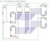
What I am trying to do is have one 7 seg display have 2 separate inputs controlled by a switch. So it receives a signal from one IC to display the numbers, flick a switch, and the first IC turns off and a second IC connected to the 7seg turns on controlling what is displayed. Keeping what was displayed when switching is not necessary. I have attached a diagram to try to better explain what I am talking about.

Thanks in advance for any help.

Ben
 

Attachments

  • 7 Seg 2 input.JPG
    7 Seg 2 input.JPG
    36.7 KB · Views: 169
rb0 is to be held high or open when an o/p is desired so you will have to connect a gnd inorder to disable them.As far as rb1 is concerned it concerns the decimal i/p so i dont think you need to connect it to a switch
 
Last edited:
Have you considered using a (two) 74LS257 to select between the two inputs. This would be the more usual way to achieve what you require.

Mike.
 
Have you considered using a (two) 74LS257 to select between the two inputs. This would be the more usual way to achieve what you require.

Mike.

There will never be an occasion where both inputs will be sending a signal (Turned on) at the same time so your options seems a little overkill to me. Would I just be able to put a diode either side of the connections to the 7seg to stop the signal passing through to the other output?
 
Last edited:
I assumed you were asking for suggestions of how to achieve what you described. Two LS257s feeding two LS48s does this and is still only 4 chips. If this isn't what you were after then what is your question?

If only 1 set of signals will be present at any one time then why do you need the switch, why not just OR the incoming signals together?

Mike.
 
Sorry I got a little confused. I was looking at the output to the 7 seg and ways to switch the a - g outputs. That's why an outsider point of view is so good. I got so focused on that, I thought you were suggesting 2 chips per 7 seg. Not one chip to switch the bcd input & making the need for only 1 74ls48. Yes an or gate will work fine. Do you think a cd4071 be suitable?

Ben
 
An ordinary Cmos gate or inverter can drive only one 74LSxx input when it has a 5V supply. It can't drive a 74xx input.
 
Status
Not open for further replies.

Latest threads

New Articles From Microcontroller Tips

Back
Top