Continue to Site

Welcome to our site!

Electro Tech is an online community (with over 170,000 members) who enjoy talking about and building electronic circuits, projects and gadgets. To participate you need to register. Registration is free. Click here to register now.

  • Welcome to our site! Electro Tech is an online community (with over 170,000 members) who enjoy talking about and building electronic circuits, projects and gadgets. To participate you need to register. Registration is free. Click here to register now.

5volt 7amp regulated psu on the cheap

Status
Not open for further replies.

tin

New Member
Hi all.

Im trying to work out a good way to turn 12v (IE car power) into 5v @ approx 6amps. I want to make it on the cheap, so Im hoping to do it with parts scabbed from old AT and ATX computer power supplies.

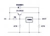
So far Ive found 1 7805 a few various negative 5v regulators and a bunch of high current switchmode power transistors (2sc2625 is one there is a few of).

Im under the impression that I could do a negative regulator and simply reverse the polarity at both ends. Am I on the right track here? Or am I even on a track at all?
 
Find a high current PNP transistor [the 2sc2625 is a NPN].
Wire it to boost the current of the 7805.
The 10 ohm resistor should be at least 2 watts.
Put the regulator & transistor on a common heatsink. [insulated]
This should give you the 6 amps.
Regards
 

Attachments

  • 7805current_boost2.jpg
    7805current_boost2.jpg
    22.7 KB · Views: 7,515
Is there a way to do it with the NPN transistors?

I do have a 7905 around in the collection of junk.

Can I do it on the negative like that?


I have looked for a PNP, but no luck, thats why Im asking about this negative method.
 
Substitute the 7805 for the 7905, use an npn pass element wire it as the above circuit......this will give a neg output wrt gnd........be sure to check the pinouts of the 7905......not the same as the 7805
 
thanks. Thats just what I wanted to hear. :)

Well, I guess Ill be building a small prototype tomorrow then. Hopefully I can make it happen.
 
This looks like exactly what I need! I hate analog design, especially BJT's, I've forgotten most everything about them except output = beta * body current or something like that :D

I need a 5v power supply that can supply about 3 amps (1.7 for cellular modem, 200 mA for GPS IIRC, and a few hundred mA for microcontroller). This design should give ample room for excess current draw! Found it on google... hopefully its drop out voltage at 3 to 4 amps is not that high, would PSPICE simulate that?
 
bleh... nm about the dropout voltage, I wasn't thinking of it properly. Don't care about dropout, voltage rails are over 12v
 
Noggin said:
This looks like exactly what I need! I hate analog design, especially BJT's, I've forgotten most everything about them except output = beta * body current or something like that :D

I need a 5v power supply that can supply about 3 amps (1.7 for cellular modem, 200 mA for GPS IIRC, and a few hundred mA for microcontroller). Found it on google... hopefully its drop out voltage at 3 to 4 amps is not that high, would PSPICE simulate that?

Why use P spice to determine the drop out? That sort of info would be to hand using the manufacturers data sheet.....
 
Yeah, I was thinking of dropout voltage improperly. I thought of it as the drop in output from the target voltage at max current instead of the drop from the rails.

I don't know if that made sense.... example, assume dropout voltage is .5 volts at 4 amps. I was thinking that the MAX output is 5v (target output) - .5v (dropout) instead of 12v (rail voltage) - .5 v. But I realized I was wrong ;)
 
Mosfet, in Your circuit the 10ohm resistor i think 1ohm, because the pass-transistor must open, when the current of 7805 reached about 1A, and this voltage drop open the transistor. For 7A output current i recommend 0.8...1ohm 8...10W resistor.
 
As the current flows through the 10 ohm resistor, the voltage drop increases to .65 volts which turns on the pass transistor. A smaller value, i.e. 1 ohm would cause LESS current to flow thru the pass transistor. With a stong pass transistor it could be increased to 20 or 30 ohms. Very little current actually flows through the regulator.
 
If the regulator is mounted close to the pass transistor good thermal conduction occurs.
The thermal overload shut-down in the regulator will protect the pass transistor from overheating.
Short lead lengths will improve transient response also.
If one needs even more current several more pass transistors can be wired in parallel.
In this case change from 10 ohm to 30 ohm.
I have used this circuit with 7809, 7812, 7815 & 7824 regulators also.
Regards Sebi.
 
Status
Not open for further replies.

Latest threads

New Articles From Microcontroller Tips

Back
Top