Continue to Site

Welcome to our site!

Electro Tech is an online community (with over 170,000 members) who enjoy talking about and building electronic circuits, projects and gadgets. To participate you need to register. Registration is free. Click here to register now.

  • Welcome to our site! Electro Tech is an online community (with over 170,000 members) who enjoy talking about and building electronic circuits, projects and gadgets. To participate you need to register. Registration is free. Click here to register now.

555 Timer Pummer

Status
Not open for further replies.

Krumlink

New Member
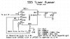
I was getting Bored, so I started prototyping "Pummers". Pummers are little LED Flashers commonly powered by Solar Light. I designed this one to run on a battery at roughly a 91.5% Duty Cycle. 555(1) Creates the 91% Duty Cycle (around 1 hertz) while 555(2) Inverts it, so that it is now a 9% Duty Cycle. The schematic is attached and was made With Express PCB (fun and easy software).

The 3300uf capacitor makes the LED fade in, giving the Pummer Effect.

If you use a 7555 you can operate your Pummer at 2.4V. I did not put a reisistor on the LED, because I intended it to be a White or a Blue SuperBright. It will appear to be VERY Bright :)

If you have any problems, questions, or comments, Post. Remember, there is a thin line between constructive critism and insult.

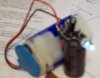
I will post Pics of the finished Pummer soon.

(THIS IS ALSO GOING ON MY WEBSITE FOR YOUR PLEASURE :D)
 

Attachments

  • 555 Timer Pummer.JPG
    555 Timer Pummer.JPG
    45.6 KB · Views: 7,970
Last edited:
You only need one 555 timer, if you connect the LED from pin 3 to +V.

You don't need a 10nF capacitor on pin 5 with CMOS 555s like the TS555 or 7555.
 
Oh yeah thats right, I forgot that the 555 can sink reverse (inverts the doody cycle). Oh well, I will still build it as shown in the schemmy. Even though it adds a level of complexity, it is good for demonstrating the 555's capability.
 
I updated the schemmy and included a pic of the final thing.

The reason I include just one 555 in the 91% duty cycle, was because the 9% duty cycle was not enough to charge the Capacitor of any large amount, and then the Cap would just discharge, therefore it would not work. With the updated version, it looks and works much better, making it easier.
 

Attachments

  • Pummer.JPG
    Pummer.JPG
    50.2 KB · Views: 531
Also, this thing is TINY. It can fit on the head of a Quarter easily (not counting the AA batteries :D
 
The output current of a 555 is over 200mA. It will destroy an ordinary LED that has a max allowed current of only 30ma.
But maybe your battery is old and doesn't have enough voltage to fry a 3.5V white or blue LED.
 
I really don't understand the purpose of C2 (3300uF) between pin 3 of the 555 and ground. If you want a fade effect put a resistor in series with pin 3 and leave C2 across the LED.
 
Last edited:
Krumlink said:
I updated the schemmy and included a pic of the final thing.

The reason I include just one 555 in the 91% duty cycle, was because the 9% duty cycle was not enough to charge the Capacitor of any large amount, and then the Cap would just discharge, therefore it would not work. With the updated version, it looks and works much better, making it easier.

Increasing the duty will cause the battery to get low quickly.isn't it?

What about reducing the capacitor value? something like below 1000uF?
 
Last edited:
It was a new circuit that I designed, so of course there is going to be problems :D
 
Brian Hoskins said:
The term "Pummer" is a new one for me.

Brian

me too! I don't know what the word means... 555 + led = blinky light in my book!

however, it appears to be a popular thing none the less... must be a generational gap or two in there?

https://www.google.com/search?q=pummer

according to beam wiki, the pummers are only supposed to do their thing at night, sleeping (and charging) during the day.

sounds like a good use for a 6 pin microcontroller!
 
Bah, it looks like a pummer, therefore tis a pummer :D
 
Status
Not open for further replies.

Latest threads

New Articles From Microcontroller Tips

Back
Top