Hello all. First post, so be gentle....
I have built and installed a delay circuit using two 555 timer pcb's into my car so that a brief press on either of it's operating switches will make the indicators work for a pre determined time. I came across this feature on a hire car once and quite liked the convenience when overtaking.....just hit the stalk (or the buttons in my case) and the indicators will flash on their own 3 times (or whatever you set it to).
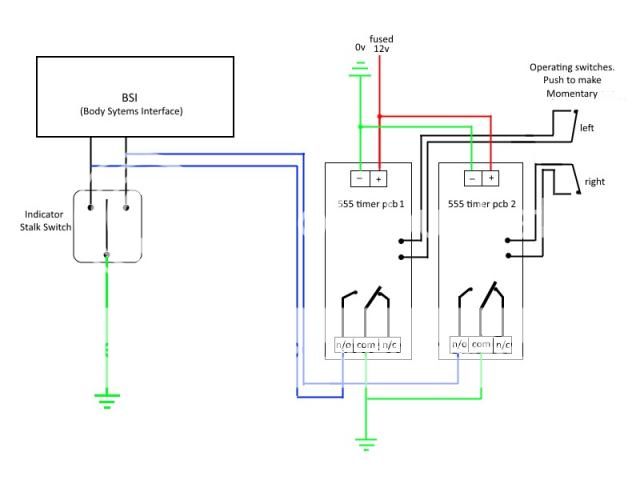
It works absolutely fine utilising two very conveniently located OEM push switches.... one on the end of the wiper stalk for the right and one on the indicator stalk itself for the left. It was not possible to use the stalk itself to trigger the 555's as it upset the two data lines coming from the BSI unit. Normal functioning of the indicators remain unimpaired.
The way these 555 pcb's operates is as follows.
They are powered up permanently. When one or other of the momentary push switches is closed and released, it starts the timing sequence in the 555. The on board SPDT relay changes over and places 0v (vehicle earth) on one or other of the data lines from the BSI. This causes the indicators to blink. After a pre-determined time, 555 chip times out and releases the relay, thus removing 0v from the data line and the indicators stop blinking.
The problem I get is that when I turn on my headlights (55W HID) the ignitor circuit for those arc bulbs seems to be putting a huge spike across the 12v system and both the 555 timer pcb's self trigger.
I think I need some sort of suppression somewhere on the supply line but don't know what/where to put it.
Any ideas?
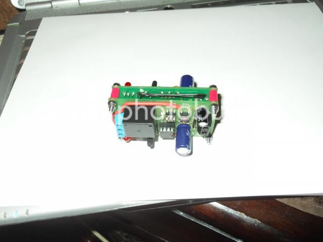
The two 555 pcb's piggy backed together.

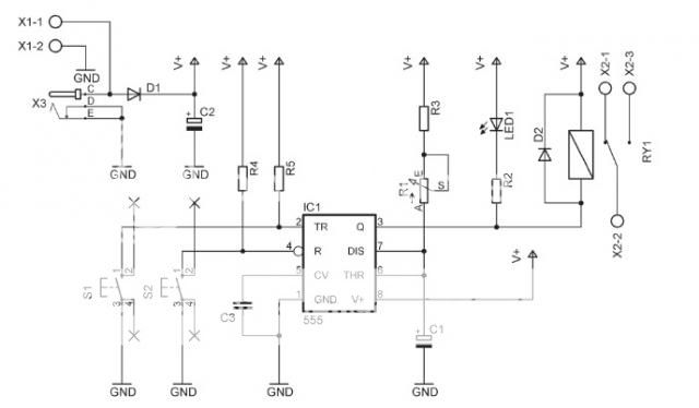
The circuit.

I have built and installed a delay circuit using two 555 timer pcb's into my car so that a brief press on either of it's operating switches will make the indicators work for a pre determined time. I came across this feature on a hire car once and quite liked the convenience when overtaking.....just hit the stalk (or the buttons in my case) and the indicators will flash on their own 3 times (or whatever you set it to).
It works absolutely fine utilising two very conveniently located OEM push switches.... one on the end of the wiper stalk for the right and one on the indicator stalk itself for the left. It was not possible to use the stalk itself to trigger the 555's as it upset the two data lines coming from the BSI unit. Normal functioning of the indicators remain unimpaired.
The way these 555 pcb's operates is as follows.
They are powered up permanently. When one or other of the momentary push switches is closed and released, it starts the timing sequence in the 555. The on board SPDT relay changes over and places 0v (vehicle earth) on one or other of the data lines from the BSI. This causes the indicators to blink. After a pre-determined time, 555 chip times out and releases the relay, thus removing 0v from the data line and the indicators stop blinking.
The problem I get is that when I turn on my headlights (55W HID) the ignitor circuit for those arc bulbs seems to be putting a huge spike across the 12v system and both the 555 timer pcb's self trigger.
I think I need some sort of suppression somewhere on the supply line but don't know what/where to put it.
Any ideas?
The two 555 pcb's piggy backed together.

The circuit.


