Continue to Site

Welcome to our site!

Electro Tech is an online community (with over 170,000 members) who enjoy talking about and building electronic circuits, projects and gadgets. To participate you need to register. Registration is free. Click here to register now.

  • Welcome to our site! Electro Tech is an online community (with over 170,000 members) who enjoy talking about and building electronic circuits, projects and gadgets. To participate you need to register. Registration is free. Click here to register now.

555 frequency stability?

Status
Not open for further replies.

bruno

New Member
My 555 timer isn't doing what it should do, or maybe it's just me?

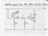
I have a 555 timer circuit operating as an extended duty cycle astable timer. The frequency generated is used to switch high power LED's which 'strobe' to freeze the motion of a spinning sculpture. Basically a stroboscope. This is all good, I have tantalum type capacitors, metal foil type resistors and they all give a good clear signal. The only problem is that over time (90 sec) the frequency of the flashing LEDs increase so the spinning wheel is not frozen, but scrolling the other direction. The same thing happens time and time again.

What's going wrong? I have 5, 47uF capacitors in series could this cause some kind of build up over time? Is it the type or quality of the 555 timer? The 555 operates a mosfet which switches the high power LEDs, could there be something there? The wheel is spun by an invertor driven three phase motor.

Please help. I feel like I'm going round in circles, that's the problem
 
Synchronizing an oscillator is almost impossible without feedback from what it's supposed to be synchronizing with. I might have said you could synchronize to the power line frequency, which is very stable, but you used an inverter. At that point, the frequency of the inverter could be drifting, too!

You need a way to tell the timer what the sculpture is doing. Somebody here might be able to help. At least I can tell you what's wrong.
 
Hi Bruno,

if I got it right you are using 5 pieces of 47µF in series for the timing capacitor.

Electrolytic caps have a high tolerance (usually ±40%) and the higher the initial value the greater is temperature drift.

Using the CMOS-version of the timer you could use one cap of smaller value like the WIMA FKP-2 with a tolerance of 2.5%

Boncuk
 
Synchronizing an oscillator is almost impossible without feedback from what it's supposed to be synchronizing with. I might have said you could synchronize to the power line frequency, which is very stable, but you used an inverter. At that point, the frequency of the inverter could be drifting, too!
Agreed, using the powerline is normally how it's done.

If you need an inverter make sure it's a good one which uses a crystal to control the frequency.
 
How stable is the supply voltage to 555? What is value of the timing resistor(s), and the capacitor? Are you using appropriate bypassing capacitors across the 555 power pins? What is the load that 555 is driving?

If you posted your schematic diagram, we wouldn't have to play twenty questions
 
Last edited:
Perhaps you could synchronize the strobe to the inverter frequency.
 
My 555 timer isn't doing what it should do, or maybe it's just me?

I feel like I'm going round in circles, that's the problem

But if you synchronized your timer to yourself, it would appear you're standing still. :D

Consider some sort of position sensor to keep the timer synchronized with your sculpture. Perhaps a small magnet and hall effect sensor.
 
Last edited:
hi bruno,
Unless I am missing some point, why do you need an oscillator to generate the LED strobe pulse.
Position a magnet on the sculptures table and trigger a Hall effect device with the magnet as it rotates and use the output to strobe the LED's
By positioning the magnet at required point you will be able to get the LED flash to occur at any preset point in the statues rotation.
 
Hi Eric, if he just synchronized the timer to the sculpture with a magnet/hall effect sensor, he can control the "on" time of the LED. Alternatively, he could just use the timer in one-shot mode. Either way would be fine.

On the other hand, if he left it in multivibrator mode, he could switch between synchronized and free-running mode, for some even cooler effects. :)
 
Last edited:
Hi Eric, if he just synchronized the timer to the sculpture with a magnet/hall effect sensor, he can control the "on" time of the LED. Alternatively, he could just use the timer in one-shot mode. Either way would be fine.

hi Danny,
I agree.
I wonder what the sculpture is.?:rolleyes:
 
Leaving the 555 behind

Hi all. Thank you for the replies I think I may be getting somewhere. I think you are right I may have to drop the 555 timer and go with a hall effect sensor to generate the pulse.

The sculpture is a zoetrope which animates 3D figures on a disc. There are 18 different movements so I need 18 flashes per rotation.

If I put a hall effect sensor near the edge of the disc and had 18 magnets on the underside of the disc I would get 18 pulses per rotation, right? I could use this pulse to activate the gate on my MOSFET which would switch the LED's? I have attached an image of my proposed circuit. Could you let me know what you think and if you see any problems (or how many!)

Thank you and I'll send a photo of it when it's all working!
 

Attachments

  • hall..jpg
    hall..jpg
    26.1 KB · Views: 282
Hi, old thread but relevant to what I am doing. Also building a zoetrope, but I need 10 strobes per rotation, and for each strobe to be ~25ms regardless of the wheel speed. I am using a hall effect sensor tied in with a one-shot 555 timer circuit jut like the leftmost diagram in the attached image (using 1 uF for C and 27K for R), but the circuit is not functioning as planned: ie the hall effect sensor makes pin 3 go high (an LED) as long as the magnet is within range. So the 555 is not one-shotting, the circuit is running as though the LED is hooked directly to an LED.
I have the hall effect sensor hooked up red to (+), black to (-), and green/output to pin 2. I have a 10K resistor from pin two to (+). Without that 10K resistor, pin 3 and the LED goes high and *stays* high indefinitely.
Help will be greatly appreciated.
Thanks
EB View attachment 65980
 
555

The 555 doesn't like the trigger to stay minus, so it might work ok when spinning. If it doesn't spinn fast enough try this: If you ac couple the input it will fire once then wait for the next negitive pulse.
 
Thanks for the reply! It was a goofy mistake anyways - by holding the magnet over the sensor, I was allowing the one-shot circuit to go high repeatedly, which happens so fast (durn electricity) I thought it was just not working. I was basically just holding the switch closed. That is a great suggestion though and I just might use that for something coming up
Cheers
EB
 
Status
Not open for further replies.

Latest threads

Back
Top