Continue to Site

Welcome to our site!

Electro Tech is an online community (with over 170,000 members) who enjoy talking about and building electronic circuits, projects and gadgets. To participate you need to register. Registration is free. Click here to register now.

  • Welcome to our site! Electro Tech is an online community (with over 170,000 members) who enjoy talking about and building electronic circuits, projects and gadgets. To participate you need to register. Registration is free. Click here to register now.

500+V power supply from 9V battery using ZVS

Status
Not open for further replies.

chembot

New Member
Hi, I'm pretty new to electronics and trying to get a HV low amperage DC power supply, somewhere in the range of 500-1kV.

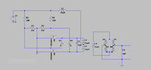
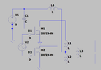
I have a basic ZVS set up, hooked up to a transformer and a rectifier. I was hoping to get an arc through the gap to make sure it works. With a 1:100 ratio on the coil it should produce around 900V, which should be enough to ionize at least 2mm of air. From what I understand, each half of the center tapped coil should generate a half sine wave, out of phase with each-other? That should generate a sine wave with 900V peaks on the other side of the transformer? With the rectifier and capacitor it should smooth out.

My question is is a 9v battery enough to drive this circuit and get HVDC? Or am I misunderstanding how the circuit works?
 

Attachments

  • circuit 1.png
    circuit 1.png
    17.8 KB · Views: 289
You are unlikely to get enough current from a normal 9V battery for it to work for long, if at all.

It would probably need some capacitors across the DC input, to provide the current pulses without too much voltage drop - eg. a reasonable size electrolytic in parallel with a plastic film cap to handle high frequency edges.

Those so-called ZVS oscillators are not very efficient to start with as both transistors are on for part of each half cycle (so not very much not "zero voltage switching"), and whatever current you draw at the output will need 100x more from the battery, not allowing for those inefficiencies.

If it works properly with an adequate power source, you could get rather more than 100x input voltage, as the transformer primary should be resonating, boosting the drive.

Also note that air breakdown is approx. 3KV per millimetre.

Make sure you use high speed diodes such as fast recovery or Schottky types; normal rectifiers turn off rather slowly and are not suitable for high frequency circuits.
 
Thanks for all the info!

My worry with using capacitors was that with pulsed DC would give a less consistent output, but with enough HV capacitors that should be mitigated. Also, to get the capacitor to discharge in pulses could I just hook it up to a zener diode?

If ZVS oscillators are inefficient, what would be a better option? I had looked at a colpitts oscillator but got recommended the ZVS instead.

I hadn't realized the oscillation with the capacitor would have such an effect on the voltage, that makes sense.

And thanks for pointing the 3KV per mm, I was assuming with 3KV per cm.

I'll have to take a look at the diodes since I'm not sure if they're high speed, that might be why the circuit isn't producing anything.
 
My worry with using capacitors was that with pulsed DC would give a less consistent output, but with enough HV capacitors that should be mitigated.
Capacitors across the DC input are purely to average out the current load on the power source, as the current draw varies drastically throughout each oscillator cycle; nothing to do with "pulses" ?

I don't know what to suggest in the way of other circuits; my preference would be a separate oscillator driving the two output transistors, but driving FETs at high frequencies is not simple, so bipolar transistors may well be better.

eg. The IRFZ44 has 1900pF gate capacitance, which takes current to charge and discharge each cycle before the device switches fully on or off.
 
I misunderstood what you meant by using capacitors. Thanks for explaining that.

Hooking up a simple oscillator to the gate of the FETs should have about the same effect as having them drive each other, although the circuit could be simplified.

Something like this? Except possibly with bipolar transistors instead.
 

Attachments

  • circuit 2.png
    circuit 2.png
    25.9 KB · Views: 239
Possibly, but without the diodes at the gates, or the FETs will never turn off.

Use low value resistors in series with power MOSFET gates, typically anything from eg. 47 Ohm down to a couple of ohms, depending on the current capability of the drive circuit.
 
As mentioned by rjenkinsgb you will need fast recover diodes, but it is unlikely that you will find a Schottky diode with a sufficient revers voltage rating. Consider the Ultra Fast diodes (UF4007, etc.).

If you don't need much current you might find a flyback power supply to me more suitable for this kind of use. For one thing, the PIV of the diodes only has to be a tiny bit more than the peak output voltage, for another, you only need one switching transistor. Just a thought.
 
Status
Not open for further replies.

Latest threads

New Articles From Microcontroller Tips

Back
Top