Continue to Site

Welcome to our site!

Electro Tech is an online community (with over 170,000 members) who enjoy talking about and building electronic circuits, projects and gadgets. To participate you need to register. Registration is free. Click here to register now.

  • Welcome to our site! Electro Tech is an online community (with over 170,000 members) who enjoy talking about and building electronic circuits, projects and gadgets. To participate you need to register. Registration is free. Click here to register now.

4A 16bit? digital power supply

Status
Not open for further replies.

MrDEB

Well-Known Member
Got to looking at different bench power supplies and using an LM317 seems the easiest method but only 1 Amp unless you follow the data sheet design.
A simple pot on the adjustment pin is really all that is needed but lets enhance the power supply with a pic and an LCD.
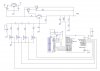
This schematic is my first draft and maybe needs adjustments here and there.
AND yes 4 amps as per data sheet page 17
Reason for this is I purchased two of the tiny power supply modules off of Ebay and one won't change the voltage. Stuck on 10v.
Just need an LM317 to bread board circuit.
Thinking of using all 1/2w resistors??
 

Attachments

  • schematic pwr.jpg
    schematic pwr.jpg
    323.6 KB · Views: 152
You mean 16 steps; not 16 bits, right?
 
the mosfets are logic level p channel mosfets that are controlled by the pic, thus IMO are not overkill.
I need to adjust the resistor values accordingly but this is a starting point. The 2k pot is for fine adjustment if desired. Thinking of putting a resistor in series with the pot to prevent the LM317 adjustment from going too low.
Plan to use two tactile switches for UP/DOWN to select desired voltage. For accuracy, 1% resistors should be used as well as add more steps.
 
What is the minimum output voltage (when port value =1111)?
What is the maximum output voltage (when port value=0000)?
Presumably you want 15 equal steps between Vmin and Vmax?

the mosfets are logic level p channel mosfets that are controlled by the pic...
The IRLZ44N you show is an NFET. Since the source will need to be tied to PICground, you should be using NFETs.

To make a true R-2R ladder, the inputs need to be switched from 0V to some other reference Voltage, not just either ground or floating.

I would use a true 8bit Dac driven directly from the PIC port pins, and then buffer that to make a true linearly-variable power supply. The 1.25V offset created in the LM317 is going to be a pain in the backside...
 
It is a 60 V, 50 A part in a 22 V, 1 mA application. 25,000-to-1 seems like overkill to me. Plus, $3 each seems high for this application.

You don't say what "too low" is, but note that an LM317 by itself cannot regulate down to 0 V. However, I don't think that will matter - your minimum output voltage with all four FETs are on is over 10 V.
To make a true R-2R ladder, the inputs need to be switched from 0V to some other reference Voltage, not just either ground or floating.
ak
 
Last edited:
going to look for a smd logic level mosfet instead of the TO220. I want to mount this on a circuit board using smd. Would need to have 10 boards made from Elecrow.
But first breadboard and test.. In theory it should work.
If and when I get that far then circuit boards will be available.
 
Sorry, but this all seems a bit 'naff' - only 16 levels isn't very good resolution at all.

If you want a processor and LCD PSU, how about this cheap kit - I built one and it's excellent.

https://www.banggood.com/0-28V-0_01...it-Current-Limiting-Protection-p-1060253.html

It actually uses the processor for the regulation, monitoring the output voltage and current (via A2D) and regulates the output accordingly using an R2R D2A.
 
going to look for a smd logic level mosfet instead of the TO220. I want to mount this on a circuit board using smd.
The 2N7000 or 7002 is a classic part for this application.

What is the output voltage range you wish to achieve?

ak
 
GREAT find Nigel
looks like a nice kit
need to reconsider my project.

Yes it's really nice, you can get a matching heatsink and fan for it as well.

I also bought a switch-mode 24V PSU from them, and modified it to give a higher voltage - it was cheaper and smaller than a conventional mains transformer.
 
There are far easier ways to accomplish more for less these days. The modules you can buy for far less than you can even purchase the parts are incrediable.

If you want an awesome bench supply, purchase one of these modules - they are available in a number of max voltage/max current versions. You can accurately set the desired voltage, current and power limits on these small modules. You supply the DC source and the module does the rest. Note that there are slightly different versions, including some with included thermostatically controlled fan.

ps1.jpg

To get something more on the order of what MrDEB is considering, order these modules (icluding cases) from Banggood. Supply a DC source, preform a simple calibration procedure and set the voltage you want to the closest 4mV. Read the voltage and current on the LCD display. Do notice the $25 price from Banggood is for five modules, including cases.

ps2.jpg


ps3.jpg
 
I purchased two of the small modules Jonsea posted and they work but one of them is stuck on 10v. need to disassemble and maybe just on of the tactile switches is stuck.
 
Status
Not open for further replies.

Latest threads

New Articles From Microcontroller Tips

Back
Top