I knew it can be somehow calculated... made and formula
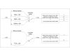
V1 and V2 is known
you set just R2
Voltage between R1 and R2 = V1 and voltage between R2 and R3 = V2
R1 = (R2+R3)*(V/V1-1)
R3 = R2*( (V/V1) / (V/V2-V/V1) )
took me some minutes, but made it
")
i mean the formula....
transmission line is few centimeters at one application and 3meters at the other one...
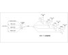
I checked the switch and it switch to the ground via resistor... I connected another fixed resistor (500ohm) from positive to the switch output and it gives me 0,14V, 2,9V, 6,23V and 9,39V so there will be 4 ranges
0,01V - 1,0V (calculated values R1=1 111 111Ω R2=100 000Ω R3=1 010Ω)
1,9V - 3,9V (calculated values R1=8 100Ω R2=2 000Ω R3=1 900Ω)
5,15V - 7,15V (calculated values R1=4 850Ω R2=2 100Ω R3=5 150Ω)
8,40V - 10,40V (calculated values R1=1 600Ω R2=2 100Ω R3=8 400Ω)
Just to put to E24 values and try it, hope tomorrow have enough time to try it
Thanks a lot for helping me out