Continue to Site

Welcome to our site!

Electro Tech is an online community (with over 170,000 members) who enjoy talking about and building electronic circuits, projects and gadgets. To participate you need to register. Registration is free. Click here to register now.

  • Welcome to our site! Electro Tech is an online community (with over 170,000 members) who enjoy talking about and building electronic circuits, projects and gadgets. To participate you need to register. Registration is free. Click here to register now.

4 Digit 7 Segment Display Module Design

Status
Not open for further replies.

ilias.cas

New Member
Hi,
I m going to design a 4 digit 7 segment display module. I want to use about 10 to 15 such modules using 89V51RD2.
I want to implement it by multiplexing method making use of 4511. Each module could be selected individually and data is latched on them.
Here are some ideas i got...
1. Use a 4511 for each display. (4 no.s in each module)
2. Data to be written to BCD inputs using uC 8 bit port where display selection can be done by a decoding ic 138.
3. Or data can be written serially to a 16 bit serial in parallel out shift register IC on each module.

I just want to implement with minimal pin usage and wiring. Rest I can handle in code.
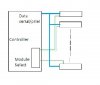
Check out the block diagram and please suggest the best solution. I hope there are many consistent members on this site who could have already done this.
 

Attachments

  • eto.jpg
    eto.jpg
    65.5 KB · Views: 464
rather than making direct single out put to select modules, you can work out to select 7 segments like this
to display a 7 segment you need 4 bits ( for 0-9)
15 modules totally have 15x4=60, 7 segments. you need 6 bit data from uC to give to address decoder to select addresses.
if i am correct you need minimum 11 out puts. may be the way you told also will tell the same.
 
I'm not sure I understand how you want to interface to the 4-digit display modules.

Do you want static or multiplexed 'modules'? That is, do you want to send data once to each 4-digit 'module' and have that module retain and display that data, which implies 32-bits of latched data for each 'module', or do you want to continually drive each digit of each module (multiplexing), which would require some 'overhead' on the host microcontroller?

If I understand correctly, you're talking about using four (4) '4511 ICs in each module. Does the '4511 latch data? If not, then you might consider using four (4) daisy-chained 74HC595 ICs in each module instead of the '4511 ICs. You would connect all of the <SER> pins together and all of the <SCK> pins together on each module and drive these paralleled <SER> and <SCK> lines using two pins on the microcontroller. Connect the <RCK> (latch) pin on each module to a unique line on the microcontroller or multiplexer IC. When you update an individual display module you would send 32-bits of display data, which all the modules would receive in parallel, but you would only "latch" data onto the outputs on one of the modules by pulsing its <RCK> (latch) pin. Since the 74HC595 has an Output Enable pin, you could connect them all together in parallel and drive them with a PWM pin from the microcontroller for 'global' PWM brightness control. So you need two (2) pins for the combined <SER> and <SCK> buss lines, four (4) pins for a 1:16 decoder, and one (1) pin to pulse the decoder enable line to output the <RCK> latch pulse to the modules. Seven (7) pins, or eight (8) pins if you decide to use PWM brightness control.

Cheerful regards, Mike McLaren, K8LH
 
Last edited:
ilias.cas,

After thinking about it, I think you can use 5 pins instead of 7 pins since you only need to address the decoder ICs when you send the <RCK> latch pulse. That means you could use two of those address lines as <SER> and <SCK> lines to load all of the 74HC595 shift registers and then set the decoder A0..A3 address lines and then send the <RCK> pulse through the decoders to latch data onto the ouputs for the selected module. You can also use those A0..A3 lines to drive a switch matrix when not updating one of the display modules.

Regards, Mike
 

Attachments

  • Driver Mux.png
    Driver Mux.png
    19 KB · Views: 882
Last edited:
Thanks Mike. It was a eye opener. You made it pretty simple. I ll get working on it. But I have few changes to raise.
1. I have to use Serial data to be driven by RXD TXD lines (Mode 0)
2. And can I make use of (2)74F675A instead of (4)74HC595 in each module?
3. Do I have to use any buffers if my module count increases?

Thanks and Regards
ilias
 
Last edited:
1. I have to use Serial data to be driven by RXD TXD lines (Mode 0)?
Not sure on your particular mcu. I usually bit bang the clock and data signals. Assuming 16 modules, I would use a display array with 64 elements, each element containing 0..9 values, and the driver would use values from that array. Perhaps something like this;
Code:
  unsigned char display[16][4];      // 16 modules, 4 bytes/module

  const segdata[] = { 0b00111111,    // '0'  -|-|F|E|D|C|B|A
                      0b00000110,    // '1'  -|-|-|-|-|C|B|-
                      0b01011011,    // '2'  -|G|-|E|D|-|B|A
                      0b01001111,    // '3'  -|G|-|-|D|C|B|A
                      0b01100110,    // '4'  -|G|F|-|-|C|B|-
                      0b01101101,    // '5'  -|G|F|-|D|C|-|A
                      0b01111101,    // '6'  -|G|F|E|D|C|-|A
                      0b00000111,    // '7'  -|-|-|-|-|C|B|A
                      0b01111111,    // '8'  -|G|F|E|D|C|B|A
                      0b01101111,    // '9'  -|G|F|-|D|C|B|A
                      0b00000000,    // ' '  -|-|-|-|-|-|-|-
                      0b01000000 };  // '-'  -|G|-|-|-|-|-|-

  #define clk portb.0                // clk = RB0
  #define dat portb.1                // dat = RB1
  #define lat portb.4                // lat = RB4
Code:
  void WriteModule(char module)      // write module 0..15 from array
  { char work, ndx;                  //
    for(char i = 0; i < 4; i++)      //
    { ndx = display[module][i];      //
      work = segdata[ndx];           // segment data pattern
      for(char b = 0; b < 8; b++)    //
      { clk = 0; dat = 0;            // clk = 0, dat = 0
        if(work.7) dat = 1;          // if b7 == 1 set dat = 1
        clk = 1;  work <<= 1;        // shift out bit, adjust 'work'
      }                              // next bit
    }                                // next byte
    portb = module;                  // set RB3:RB0 (decoder A3:A0), 0..15
    lat = 0; lat = 1;                // latch selected module only
  }
2. And can I make use of (2)74F675A instead of (4)74HC595 in each module?
Sorry, not familiar with that device. Looks like it uses an active low latch pulse which would require active low 74HC138 decoders instead of active high 74HC238 decoders.

3. Do I have to use any buffers if my module count increases?
Sorry, I don't understand your question.
 
Last edited:
If you daisy-chain the SDATA of all devices, you don't need any '238 or '138 decoders and the wiring from the uC is simplified - each module will have connections for VCC, GND, SCLK, LATCH, SDATAIN & SDATAOUT.

To update any display, the data for all displays is sent, then latched.
 
My 3rd question was regarding Fan out capacity of Controller. Do you think if i use 10 to 16 such modules, the controller would be able to drive all of them or I have to use some other alternative?

Thanks Mike. I m working on rest of it. I need some time to take conclusions. Your advices were pretty useful.
Thanks again.

Regards,
ilias
 
Last edited:
My 3rd question was regarding Fan out capacity of Controller. Do you think if i use 10 to 16 such modules, the controller would be able to drive all of them or I have to use some other alternative?

I'm not sure what the fanout specs' are for your processor. Sorry.

Can you tell us what you're doing with this display system? As dougy83 pointed out, there are many different ways to drive those display modules. Some methods may use more I/O pins but reduce processing overhead, or vice-versa. Some methods like multiplexing might reduce the number of ICs you're using from 64-66 (for 16 modules) down to perhaps 16.

Cheerful regards, Mike
 
Last edited:
I would be happy if I could find such method in which I can use just 16 ICs for 16 modules.
Well! all I m doing is, displaying different times on each module that are saved in flash. This data to be displayed might frequently change. Every time controller is reset, controller reads appropriate data to be displayed from flash (eeprom) and display it on them. This data has to be static until i change it for next time. That is it!
Any straight solutions, will really help me.

Thanks Mike!
 
Status
Not open for further replies.

Latest threads

New Articles From Microcontroller Tips

Back
Top