I don't know what to do!
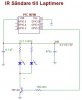
I have made a IR transmitter that is driven by 2 AA batteries (3V) look at the scematic.
But i have a problem, it is not reaching far enough!
A week ago i made a IR tranmitter with the same scematic but i used 6V instead and used larger resitors and had the led's seriell instead of parallell. That one had ways longer reach.
Why doesn't the 3V version work good?
The transitor i am using is a Darlington switch for currents up to 5A or something. But in my circuit there's just 1 to 1.5 A.
Any ideas what i should do to get it work better? Is the voltage drop in the transitor to big so that the voltage over the leds get to small? What can i do to get aroung this problem? I need to use 3V...
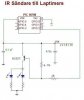