Continue to Site

Welcome to our site!

Electro Tech is an online community (with over 170,000 members) who enjoy talking about and building electronic circuits, projects and gadgets. To participate you need to register. Registration is free. Click here to register now.

  • Welcome to our site! Electro Tech is an online community (with over 170,000 members) who enjoy talking about and building electronic circuits, projects and gadgets. To participate you need to register. Registration is free. Click here to register now.

3pdt to dpdt

Status
Not open for further replies.
Rest assured, if wired exactly as drawn it will work. Not shown is the relay coil but I assume you have that covered. Deenergized the motor will run in one direction and with the relay energized the opposite direction.

Ron
 
Including the coil in the in drawing was not necessary,i am very familiar with that bit.
 
Last edited:
kit

HI folks
i keep coming across this product: 3166 - Bidirectional DC Motor Speed Controller (5-32V, 10A) on the net .
Can it reverse the direction of a DC motor hourly?
Kindly follow the link .... **broken link removed**
 
Last edited:
This thread is getting a bit wierd.

1. Ron's circuit is a bit wierd because he uses NC and NO contacts, rather than looking like an SPDT switch.
2. Components are missing in ron's diagram.

There needs to be directional limit switches in the circuit. They can be created with a diode and a microswitch. The diode tells the circuit which direction the switch will work. It has to open in the direction of the diode. You place two of these switch/diode combination in parallel and place it in series with the circuit. The diode would be reversed in one of the switch/diode circuits.

A timer is necessary that has a 2 hour, 50% duty cycle and that would control Ron's circuit with the addiitional limit control.

Does this make sense to you?

The controller you referenced, seems to use a potentiometer where center is the off position. Turning right or left increases the speed depending on how far you are away from the center position.
 
Last edited:
The quasarelectronics unit doesn't seem suitable for your purpose, as it needs human control to reverse the motor and can't do it automatically. The write-up is interesting, however, as it mentions the danger of suddenly reversing a DC motor. If a relay is simply used to switch the supply polarity abruptly then excessive current can flow in the motor winding while the motor slows, stops and then speeds up in the reverse direction. This can burn out the winding.

Alec
 
One thought

Hi
your contribution does make a lot of sense.A micro limit switch is indispensable in this scenario.I think using two of these 'Omron MKS3P' relays with the NC /NO contacts crosswired like Ron suggested will do the trick.The NC contacts for instance would forward the motor whiles the NO contacts does the reversal.Energized the motor will run in one direction and deenergized,it will run in opppsite direction.
 
Last edited:
Hi folks,
there is a diagram i have copied and want to paste but finding it very difficult doing so.Please help.
 
You need to add this circuit containing the two limit switches and diodes in series with the motor in Ron's schematic. The diode needs to be picked so it has the current capacity of the motor.
 

Attachments

  • motor limits.pdf
    4.2 KB · Views: 156
Hi
your contribution does make a lot of sense.A micro limit switch is indispensable in this scenario.I think using two of these 'Omron MKS3P' relays with the NC /NO contacts crosswired like Ron suggested will do the trick.The NC contacts for instance would forward the motor whiles the NO contacts does the reversal.Energized the motor will run in one direction and deenergized,it will run in opppsite direction.

Kwamie, originally you asked about using a relay to reverse a motor. That was all you asked so using the relay you have I gave you a circuit that would reverse a DC motor's direction. I pointed out that going from one direction and doing an immediate reverse was unwise. Now as to limit switches? What exactly, in detail, are you trying to do? Are you using a device like a linear actuator? Additionally, the drawing I posted was based on a "Ladder Logic" specifically for your relay including the pin numbers.

Ron
 
Hi folks
i think reversing a DC motor with this omron MKS3P is not possible.I employed all the suggestions posted on the subject but all to no avail.I have just tried for two-three hours but it wont reverse.I think its time to call it a day and would not edge anyone to try this out cos it will be a fiasco.
I am considering some alternatives .For instance i am trying to investivate how self tuning satellite dishes fitted with linear actuators(dish motor) rotate automatically on their own.Does anyone have some experience in this regard?Has anyone used ,serviced or familiar with self tuning/rotating satellite dishes?
 
Last edited:
That reversing circuit WILL work.

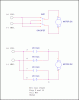
If a DPDT switch is layed out like

1 2 3
4 5 6

from the back. This means that 2 & 3 re common. For now, let's assume 3 & 6 are the Normally open contacts and 1 & 4 are thre normally closed ones, thus 1,2 & 3 are related and 4, 5 & 6 are related.

Put a wire between 3 & 4 and connect this to the power supply
Put a wire between 6 & 1 and connect to the power supply.

Take 2 & 5 and connect to the motor.

If you use a DPDT center off switch the motor will have forward, off and reverse positions.

Unless your motor has a diode across it's terminals, it will work. I will assume that you have already connected the power supply in reverse to the motor tuerminals and it reverses.

Dishes work the same way. They have two hard limits as described earlier built in. Adustible limits are rare.

Position for dishes are usually by two methods:
1. Hall effect (counts pulses); an open collector transistor and a magnet, +5V power is required
2. Optical Same deal; open collector, +5 volt power is required.
3. A micro switch that creates a pulse.

There is an INDEX position that the controller can use to find itself. A typical motion controller will reverse until it hits a hard stop and check along the way whether or not INDEX was found. It will then go in the forward direction SLOWLY until the INDEX position is found. This is standard protocol.

A 4th method which is not seen on satelite dishes is the potentiometer. Basically a resistance is proportional to position.

Now if your motor is something wierd then you may have to do strange things, The DC motor we are assuming here is a permanent magnet DC motor.

You must be able to answer this question as true:

Does the motor reverse when the polarity of the power supply is reversed on the motor?

Second:

Do you own a multimeter?
 
Last edited:
Yes i do have a multimeter.I have a number of toggle switches all of which are of good quality but they are time consuming to use.I want something which can forward/reverse without human interference.The DPDT relay will not work honest to God!In doubt ?Kindly find a miniature motor found used Radio-Cassette Hi systems and try it out.There is no way the DPDT relay can reverse a dc motor.The motor will remain at at a standstill or move clockwise,
The motor is just a prototype for trials.I want to use it for my linear actuators eventually.The linear actuator has inbuilt limit switches already.
 
Last edited:
H about an H bridge?Can it reverse /forward a linear actuator and do you have a simple schematic that can be used to construct a low cost simple H bridge?
 
Kwame, did you wire your switch thusly?

**broken link removed**

I guarantee you that this will reverse any DC motor with 2 leads (stepper motors excluded).

How did you wire your DPDT relay? This has to work.
 
Here is the full schematic sans the proper pin numbers for:
1. A power switch
2. Limit switches
3. A reversing relay with a (FWD/REV) switch

Logic and motor grounds are separate. Logic and motor power supplies are separate.
the motor supply has to agree with the motor. The logic supply has to agree with the relay coil voltage.

Does this schematic make better sense?
 

Attachments

  • Motor reverse w limits.pdf
    9.8 KB · Views: 168
The DC motor in a cassette deck has a BUILT-IN speed control. It is not reverseable. The speed control is usually built INSIDE the motor. It uses IR compensation e.g V(applied) = Vm - Im*Rm. It tries to keep Vm constant.

That's why I asked whether you CAN reverse the motor by switching the polarity. If you can't, then none of these circuits will work.
 
Kwame, attached is an image with two circuits. One uses a switch to reverse motor direction and the other is pretty much what I posted. Unless you have the relay mis-wired or something incorrectly wired the circuit will work. When the relay is energized the voltage polarity to the motor is reversed. On your relay:

Pins 1 (common) and 6 (common) should be tied to the motor power connections. Pins 3 N/O and 5 N/C are tied together and connected to one side of your power source. Pins 4 N/C and 7 N/O are tied together and connected to the other side of your power source. Just looking at either the switch or relay circuit should make it apparent that it works. Either circuit will reverse the polarity of the supply to the motor. The only way the relay circuit will not work is if there was a short that fused a pair of contacts. The drawings are self explanatory.

As to the motor. Yes, you can buy or build an H bridge to reverse polarity. The parts used would be a function of the current the motor draws under full load ratings since I assume the motor power will be fused.

Do you have a link to this motor or linear actuator?

Additionally, can you do as KISS suggest and just manually reverse polarity to the motor and have it reverse?

Ron
 

Attachments

  • Motor Reverse.gif
    Motor Reverse.gif
    13.1 KB · Views: 163
Last edited:
Status
Not open for further replies.

Latest threads

New Articles From Microcontroller Tips

Back
Top