customMotion
New Member
i appreciate the info, i will abandon the idea of mismatched caps. i have already cleaned up enough confetti. i was looking for a shortcut as usual but instead i will delve into the internet as i need more info.
Follow along with the video below to see how to install our site as a web app on your home screen.
Note: This feature may not be available in some browsers.
I would say yes.... Would a time delay relay be easier to obtain ...
Have you got any specific suggestions for a voltage sensing relay?Yes, in a fixed load application time delay relay would work but most of those cost as much as a voltage sensing relay.
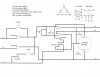
I built this based on your system. I am having a problem with it coming up to speed. It starts but turns slowly. Any ideas?
Thanks

What do you suggest?