Continue to Site

Welcome to our site!

Electro Tech is an online community (with over 170,000 members) who enjoy talking about and building electronic circuits, projects and gadgets. To participate you need to register. Registration is free. Click here to register now.

  • Welcome to our site! Electro Tech is an online community (with over 170,000 members) who enjoy talking about and building electronic circuits, projects and gadgets. To participate you need to register. Registration is free. Click here to register now.

3 Ph Motor conversion to PM alternator

Status
Not open for further replies.

tcmtech

Banned
Most Helpful Member
I suspect many of you have often wondered how difficult it is to convert a stock three phase or other similar type of induction motor into a permanent magnet alternator. I did and here is how I did it and what I have learned from it.

I have been working on this project off and on in my spare time this winter and here is what I've done so far.

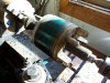
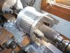
I started out with an old Wagner 7.5 Hp high service factor three phase motor. Its original specs are
208/220/440 VAC, 24/23/11.5 Amps, 1750 RPM, Service Factor 1.4, Service factor amps - 15 at 440 VAC.
Being this is a 12 lead type motor makes it possible to have many different output voltage ranges when being used as a PM alternator.

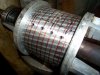
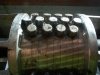
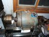
The method I chose was to simply machine the original rotor down one inch in diameter from its original dimension and counter sink four sets of 1/2" X 1" N42 neodymium magnets into it with 13 magnets making up each of the four individual poles.

The magnets are counter sunk in .520" from the surface of the machined down rotor so they are within a few thousands of an inch from the rotors original clearances to the stator. The extra .020 is due to the magnets having flat tops that dont follow the exact radius of the original rotor.
 

Attachments

  • DCP01869.JPG
    DCP01869.JPG
    329.9 KB · Views: 11,533
  • DCP01873.JPG
    DCP01873.JPG
    271.2 KB · Views: 8,585
  • DCP01878.JPG
    DCP01878.JPG
    233 KB · Views: 12,032
  • DCP01871.JPG
    DCP01871.JPG
    398.4 KB · Views: 11,866
  • DCP01892.JPG
    DCP01892.JPG
    354.3 KB · Views: 8,288
Last edited:
The first picture is the original unmodified rotor.
The second picture is the rotor after it has been marked and pilot holes have been drilled for the magnet layout.
The third picture is the rotor with the magnets epoxied into their places.
The fourth picture is the rotor after it was turned down. (the attach files function insists it goes fourth and not second)
The fifth picture is the reasembled motor set up in my lathe so I could do the power and speed testing.

The motor itself is a OFC (open fan cooled) weather proof type 215 frame size with a 1.125" shaft and weighs around 100 pounds which makes it very well built. Being a rough service type motor the bearings are considerably over sized, have grease zerks, and substantial grease reservoirs built into the end bells.

Machining down the rotor took about 3 hours total time. The holes for the magnets where done in three steps.
A 1/4" pilot hole was drilled 1/2" in. Then a 1/2" hole was drilled using the pilot hole as a guide. The hole depths were finished with a a 1/2" four fluted end mill so that the magnets sit flat on the bottom of the holes.

I used regular fast setting JB weld to hold the magnets in place. Which by the way JB weld is slightly magnetically reactive and tends to want to migrate to the ends of the magnets until it hardens up. To work around this issue I mixed all of the epoxy in the individual holes for each set of 13 magnets that made up one pole of the rotor. By doing so the epoxy is fully mixed and covers the inside of each hole. When the magnet is placed in it will pull itself into the hole displacing the epoxy around it. Once all 13 magnets are in place the epoxy must be continually worked back around the magnets as it hardens.

To place the rotor back in the motor I secured the motor stator to a bench and carefully slid the rotor back into its place by holding on to each shaft end. It goes easy and the magnets dont have an extreme amount of pull until the last inch or so of fit. Then it takes some considerable force to pull the rotor back out.
 
Last edited:
With the motor reassembled and the windings configured for the 440 volt connections I did the spin up and testing.

I was pleased that there are no perceivable cogging effects when turning it by hand with and without a load on it. However if only just one phase is shorted there is a noticeable dead spot between the poles as they cross the respective windings. With all three shorted together there is no noticeable dead spots.

My lathe tops out at 900 RPM no load in the gear range I have it at now so thats what speed I worked with during the testing.

At 900 RPM I was able to get 90 volts open circuit with the three phase output rectified and filtered with a 450 volt 2500 Uf capacitor. On an approximate 6 ohm load I was able to get 52 volts at around 10 amps where my lathe topped out at 750 RPM.

The dead short test produced far more drag than my lathe can carry through its belt drive. I was only able to get to 45 amps at a dead short for a few seconds before the belts started smoking and that was turning at around 100 RPM at best!

I had hoped for a higher output voltage but being my magnets only cover about 1/2 of the total area on the rotor for each pole its running on half the maximum individual pole size that it could be. I believe its somewhat limiting my peak voltage and likely responsible for the larger voltage drops at load as well.

Given the rough RPM Vs load curve it should still be able to produce around 120 volts at 15 amps of load at the motors stock 1750 RPM.

The overall robustness of the windings will make it a very durable direct drive alternator for a 7 foot three blade wind generator. Being the motor is now working at only a fraction of its original capacity as a generator it should be nearly impossible to burn out or damage.

Having the capacity for multiple possible winding configurations it is easily adaptable to be able to work as a high amp 12 -24 volt generator or a 120 volt unit while staying with in its original RPM range.


Still this is what an old motor and $65 in magnets with one good days worth of time can make.
The next one will get the full compliment of magnets and I will probably revise the epoxy application method as well.
 
Last edited:
G'day Tcmtech,
Great review on doing an elcheapo way of converting a 3 phase motor to a wind genny. With the 12 wires coming out you can have heaps of wiring options. 1 Y, 1 delta, 2 Y 2 Delta etc. Depending on the thickness of the wire will dictate the current you can get.

With my 3 phase conversions I machine a new rotor shaft from solid bar stock, with my 1.5kw (2hp) conversion which was my first, I used 8 off 2x1x1/2" epoxy coated N42's with a countersunk hole in the centre. I machined slots in the rotor so each slot was 42.5 degrees or there abouts then once screwed in and also super glued in I made a round mold then poured epoxy in to totally cover the mags so I could machine the epoxy for a 1mm on diameter gap. That 1.5kw conversion is hooked on my shed and the best I've seen is over 20amps @ 27 volts. My analogue 20 amp guage completly tops out when a gale comes thru. I am testing this conversion to destruction but the thing just keeps on putting out power.

With my 4kw motor conversion the next big job is counter boring 98 holes in for a total of 4 poles for 16x13mm N50 round neo's. That's just over 15 cubic " of magnets. I'll also be doing a total re-wire and first do a 1 wire test at the desired cutin. Then calculating the voltage I can then workout the turns for the thickest wire I can get in the slots. I am hoping for 2 turns of 14 gauge wire in hand if the 1 wire test what I hope.

With the jobs I have currently going hoping soon I can get working on the 4kw conversion again then I'll do a write up on it.

Cheers Bryan
 
The old Wagner motor I used is massively over wound in comparison to similar newer style 7.5 Hp motors. Plus the high service factor puts it closer to being a 10 HP standard service factor motor.

Although the service factor amps are rated at 15 per phase in the 440 VAC configuration I dont feel this old motor would have any problem holding a 40+ amp load on a DC output. The windings are all 14 gauge. If I configure it to a double delta output I think it would still push well past 120 amps continuous duty without hurting anything.

My brother has a well designed home built three axis CNC carving machine that should be able to make some nice wood blades for me on the cheap. I am planning on making a 7 foot four blade design for this motor using pine or redwood for the blade cores with a heavy outer shell of carbon fiber over them.
The intentions are to have a 7 foot blade set that can safely free wheel at 2500+ RPM if it has to. But the intentions are that the four blade setup should stumble over itself and limit its top speeds before it ever gets going that fast.
I and a friend of mine carved several homemade blade sets out of 2X6's some years ago that stood up well at that speed for many years before the wind erosion just sanded the leading edges off of them to the point they couldn't start any more.
With the four blade design I should get better low speed starting abilities and higher running torque that should be a close match this motors output numbers as it stands now.

With this wind generator I am going to follow the rest of it through to be as overbuilt as this motor is. Granted it will end up only being a 7 foot wind generator that only puts out around 500 -1000 watts and weighs some 250 pounds, but its robustness should give it the ability to easily take on anything nature can throw at it for many decades! The tower is going to be a 22 foot long 5" diameter 1/4" wall steel tube set in concrete 4+ feet in the ground.

The next motor I am going to convert is a 875 RPM 7.5 Hp industrial motor. It has the same 12 lead connection and specs as this motor does but being an 8 pole motor it only runs at half the RPM's.
I am thinking that one should work well with a 10 foot set of blades and hopefully will be able to produce around 2 - 3 KW peak.
My thoughts are to go with smaller 3/8" by 3/4" magnets but use around 400 of them fitted as closely as possible in order to get the field strengths and densities up as high as possible.
 
Great write up TCM. :) It's good to see this is still quite do-able even without luxuries like a vertical mill and rotary indexer etc.

Will you need a gearbox to use that motor on a windmill? Maybe you could just use a toothed belt like an auto cam belt etc and a couple of home made pulleys. You would have to test cut-in speed vs the generator output to batteries but I think about 2 to 1 or 2.5 to 1 would be ok.
 
Anyone with even the most basic of metal working lathe can do something like this. The actual magnet layout is very simple math and measurements. I used a drill press and a jig to hold the rotor but if necessary a good hand drill and a drill bit with a stop collar to keep it from going in to far would work well enough. Same with end milling the hole bottoms flat. Just use a drill and the right end mill with a stop collar.

This ones going to be a direct drive system. Also being I design my own grid tie inverters its easy to make one custom to the output curves that this generator will work with. I am already working on the PLR program for the GTI unit now so that actual cut in and power curves are easy to match to what I am doing.
 
Last edited:
G'day Tcmtech,
Quick question mate, did you use the decogging pdf I put in the RE Projects forum for getting the correct skew on the magnets????????

Cheers Bryan
 
I've got a couple of questions.

Why did you need to reduce the diameter of the rotary by an inch?

This might sound like a silly question by why do you need all those magnets?

I've heard it's possible to get an induction motor to act as a generator by spinning it, applying a small pulse to excite it, then it will self exciter from then onwards. The pulse might not even be required if there's enough residue flux in the rotary.

Surely all you needed to do is add a couple of small magnets to start it off?
 
Quick question mate, did you use the decogging pdf I put in the RE Projects forum for getting the correct skew on the magnets????????

Of course! :)
To get the decogging effect I used a slight variation on your thread information.
Being my motor has something like 60 slots I arranged my magnets in rows of three for each pole and the number 1 and 3 poles are offset about 1/4 of a slot width from being exactly 90 degrees to the other two. The combination of the offset and having odd numbers of rows on the magnet pole layouts worked out to give the right skewing effect. Same principle but a slightly different layout.

Why did you need to reduce the diameter of the rotary by an inch?
I reduced the rotor diameter by an inch because my magnets are and inch long and I wanted to have then embedded into the rotor core half way so they would have the greatest magnetic connection to the rotor and not to their own ends. The magnetic lines of force have to flow through the stator and the rotor and not from end to end as they would if the had been completely counter sunk.
Plus it gives the epoxy much more surface area to hold the magnets with as well. The combined countersinking and epoxy makes it possible to run this motor at higher than stock RPM's without centrifugal forces pulling the magnets off of the rotor. I think the combined magnetic force and estimated epoxy bond strengths should keep the magnets in place up to around 5000 RPM. In theory any way.
Without the epoxy and just sitting in a hole far more effort is needed to remove a single magnet from the rotor than when they are just sitting on the surface of the rotor.

I've heard it's possible to get an induction motor to act as a generator by spinning it, applying a small pulse to excite it, then it will self exciter from then onwards. The pulse might not even be required if there's enough residue flux in the rotary.

All of the magnets are needed to increase the pole field strengths so that it produces more power at low RPM's The method of using a capacitor to get an induction motor to work as a generator only works at or around the normal running speed of the motor and has a limited ability to self excite. It also tends have a limit to how much power can be taken before it looses it self excitation.

Being this has the capacity to generate power from any movement its able to produce some power at any speed no matter how slow. It may only be a few watts at a few tens of RPM's but it is generating just the same! In wind power slow speed power production still can account for a lot of usable power if its managed properly.
 
Hi there tcm thech. I have a small 3 phase Siemens motor (between 1 and 1.5KW depending on wiring voltage and frequency). It has 3 coils so it's a simple setup. It can be wired for 220V or upto 500V depending on the situation (have been trying to understand the 240V Delta configuration for single phase operation, i guess you need a startup cap). Anyway i was really interested in converting it into an alternator so that i could generate some power (40Watts or more) in a micro hydro pelton wheel system. Is there anything i need to consider before i order the magnets and start chopping up the rotor?
Should i avoid very powerful magnets? are column shapes the best or just the easiest to work with? i was thinking to use rectangular neos.
Also just wondering if you know the theory behind building an alternator without iron cores in the coils, would the coils produce more power if they were not wrapped around iron? Thanks.
James
 
Magnet wise the larger and more powerful you can fit the better.

BTW this thread is about 4 years old now so my work on this since has long been done with. :(
 
Hello agin tcmtech. I have just noticed that by offsetting the magnets you have a row of 5 of one magnetic pole followed by a row of 4 with the opposing pole, do you think it would have been better to keep the north and south poles at 5 each? Was there a reason for having North or south stronger than the other? Do you know if there are more threads on this type of conversion as it's been a few years now, ahh i've just seen your reply from earlier, thanks for that. I'll do another search around to see if i can come up with any more info. Sounds like you have moved on from generators, is there a reason for this? Are you working in a different field now? I have had some slightly different ideas when it comes to power production, if you are still interested, i am looking for other people to share the ideas with and see what we can come up with. If anything comes of it i would like to release the information to the public, but not before protecting the idea from larger organisations with a patent. Looking for like minded people to bounce ideas around.
James
 
All 13 of those magnets represent just one pole of the motor.

I moved on to other things being I have lots of surplus connections for parts and to be honest DIY PM conversions of old 3ph inductions motors is a lot of work and money that was better spent elsewhere like buying up good used AC and DC PM servos that put out way more power in a given size of motor than a homemade conversion ever would.
 
:-( just wrote a huge reply. Explaining. Well quite a lot if things. Damn iPhone. Or we'll it must be me. I'm tired. Somehow selected everything and hit return by mistake. Had it copied. But phone pasted some old rubbish from its memory. Anyway. It was a nice story. Perhaps I'll try to explain again some other time as its very late now. Basically I have many projects but little space to work or put them into practice use. I have been dismantling stators and speakers etc. since I was 10. I now live in a tiny shack in the mountains in France with shack mates. The hydro is for the shack. I have a very large PM servo motor in the UK but nowhere to put it into use right now. I'm looking for people to bounce ideas around. Not so much for these regular projects. Some concepts I would like to experiment with but not till I gain a little more knowledge. It is one of the reasons I was asking if more power could be generated if the coils were not wound around an iron core. My concepts come from a wide range of ideas not just from one or two fields in physics. If your interested we can discuss these ideas in a private message for now. Once I feel I have sufficient knowledge I will start to build some of my ideas into protos. Just very limited in space and funds right now. So u don't want to spend time and money barking up the wrong tree. I know my idea can produce power. I just don't know how much yet, there are many variations on the theme. I just can't quite picture the physics behind it. It's not easy to understand invisible forces :) this is getting as long as the message I deleted by mistake. Private message me if you believe you may be interested in working on this together. I also am trying to work out a way to create dc output with fixed coils and almost no electronics. Just a moving magnet and perhaps a capacitor which wouldn't be necessary (I don't think) when charging lead acid and we are off grid and budgetless more or less. Gotta sleep now. I'm bushed! Thanks for the replies so far.
James​
 
Just to let you know I am going to Turkey for a month. Odds are I may not reply any time soon. :(
 
Just to let you know I am going to Turkey for a month. Odds are I may not reply any time soon. :(
No Problem, i'm about to goto Egypt for 11 days. Wonder if i can find any secrets hidden in the pyramids :D Really just going to go have some good times with friends and do some kite surfing. Have fun in Turkey. I'll let you know if i get anywhere with my theories. Do you know if it would be possible to put two sine waves (ac signal) together but offset the second one to fill in the missing peaks (as best as possible, i suppose it depends on the frequency). Then if one was to measure between peak to peak, would this not be close to a DC signal since it would be almost a steady signal. would the potential difference not be close to a DC signal? This is what i am currently trying to understand. The was i see it, it should be possible to add a second (or more) alternating signals out of phase to fill the troughs and then take the potential difference from peak to peak. If this is possible then would we be able to use this signal as a dc signal (lets say for charging batteries as i imagine it to be a bit of a rough dc pattern)? Then it must be possible to generate this out of phase signal by getting clever with the windings and avoiding the use for diodes? I know it sounds wrong but it seems correct to me, we are just looking at the potential difference and if the waves are filled in on the + troughs and - troughs it would no longer be alternating (once both signals get mixed) or is this simply a dead short? So the other way of doing this would be to only generate the + and then generate another + out of phase to fill in the missing part of the wave? Just some silly ideas i am playing with in my head. The other concepts i have i believe to be quite interesting. But i'm not letting the cat out of the bag yet, unless someone is interested in working on this with me.
James
 
Hi sorry know this is an old thread but is that 6 sets of poles in total (60 slots divided by 13 holes (for each pole) = 4.6)? I suppose it doesn't matter as long as it's 50% of each. Also just trying to understand more about the decogging effect, is it possible to see how you have done this in the photos? Will go check how bryan1 did it, perhaps it will help me understand this better. Thanks again for the inspiration, just trying to find a friend with a lathe now.
 
Hi sorry know this is an old thread but is that 6 sets of poles in total (60 slots divided by 13 holes (for each pole) = 4.6)? I suppose it doesn't matter as long as it's 50% of each. Also just trying to understand more about the decogging effect, is it possible to see how you have done this in the photos? Will go check how bryan1 did it, perhaps it will help me understand this better. Thanks again for the inspiration, just trying to find a friend with a lathe now.
Ahh i see now, i was thinking 60 magnets, but you mean 60 slots in the casing for the windings, i'm close to working this out now. Thanks.
 
Status
Not open for further replies.

Latest threads

New Articles From Microcontroller Tips

Back
Top