I am designing a sensor to measure the biopotential from a person (EKG)
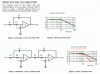
If i am trying to design a 2nd order lowpass filter with a corner frequency of 250 Hz would using a cascaded RC filter with the output voltage going into a voltage follower (lm741) be a decent approach. i have attached a picture of the circuit i am describing**broken link removed**. Will there be an issue with the capacitor connected to the + terminal of the op-amp knowing that certain frequecies will short the cap.
The output from the voltage follower will be connected to the AD202K isolation transformer in order to isolate the person under measurement from any harmful surges of current.
Just wondering if my filter choice will work under most cicrcumstances. I am new to the design realm in electronics so any help will be nice.
Mythoughts:
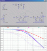
First, each RC branch's corner frequency is 250Hz yet when they are cascaded the corner frequency is 150 Hz. I am only saying this because when i simulate a BODE plot, or even plug in the values in my transfer function at 150Hz i get attenuation by a factor of .707 (-3dB). My understanding of the corner frequency is the frequency in which the circuit has half power or 20log(1/sqrt(2)). When calculated or simulated at 250Hz i get attenuation of 0.5.
Does the second branch really change the cornerfrequency?
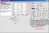
I know the second branch of the RC section (R2 and C2) will load the first part, which is why i increased R2 by a factor of 10.
Second:
The cap is only a short a high frequencies and considering my corner freq is 250should i forsee a problem?
are there other issues i should focus on?
or should i use a butterworth filter?
If i am trying to design a 2nd order lowpass filter with a corner frequency of 250 Hz would using a cascaded RC filter with the output voltage going into a voltage follower (lm741) be a decent approach. i have attached a picture of the circuit i am describing**broken link removed**. Will there be an issue with the capacitor connected to the + terminal of the op-amp knowing that certain frequecies will short the cap.
The output from the voltage follower will be connected to the AD202K isolation transformer in order to isolate the person under measurement from any harmful surges of current.
Just wondering if my filter choice will work under most cicrcumstances. I am new to the design realm in electronics so any help will be nice.
Mythoughts:
First, each RC branch's corner frequency is 250Hz yet when they are cascaded the corner frequency is 150 Hz. I am only saying this because when i simulate a BODE plot, or even plug in the values in my transfer function at 150Hz i get attenuation by a factor of .707 (-3dB). My understanding of the corner frequency is the frequency in which the circuit has half power or 20log(1/sqrt(2)). When calculated or simulated at 250Hz i get attenuation of 0.5.
Does the second branch really change the cornerfrequency?
I know the second branch of the RC section (R2 and C2) will load the first part, which is why i increased R2 by a factor of 10.
Second:
The cap is only a short a high frequencies and considering my corner freq is 250should i forsee a problem?
are there other issues i should focus on?
or should i use a butterworth filter?
Last edited: