Continue to Site

Welcome to our site!

Electro Tech is an online community (with over 170,000 members) who enjoy talking about and building electronic circuits, projects and gadgets. To participate you need to register. Registration is free. Click here to register now.

  • Welcome to our site! Electro Tech is an online community (with over 170,000 members) who enjoy talking about and building electronic circuits, projects and gadgets. To participate you need to register. Registration is free. Click here to register now.

2n2222 variant with 12v emitter?

Status
Not open for further replies.

Deeg

Member
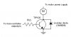
I'm working on a project that will control a 300mA 12v blower via PWM. Fairly straight-forward except that I can't find a transistor that can emit 12v in a TO-92 type package. Do I need to get a driver to handle that much voltage? I was hoping to use a simple transistor. Does a variant exist with a 12v emitter? The controlling PWM signal is 3.3v. Thanks!
 
I can't find a transistor that can emit 12v in a TO-92 type package...........Does a variant exist with a 12v emitter?

I don't understand. Are you looking for a Vb-e voltage of 12 volts?
A 2N2222a can handle much more than 12V on the collector.
Can you send a drawing?
 
Thanks for the help Ron. It's possible I have myself confused. Here's what I've got using a 2n2222 (excuse the crudeness :) ) :
View attachment 68591
The multimeter leads are attached to the emitter and ground from 12v power supply. When I supply 3.3v to the base I would expect the emitter voltage to be 12v but according to my multimeter it's just under 3v. When I send 5v to the base the output is just under 5v. I've verified that I'm getting 12v from the power supply.

The control signal (the 3.3v or 5v) is coming from a IOIO board and I've measured the voltage and it all seems fine.

The diagram shows exactly how it's wired: 12v PS directly to collector, IOIO voltage pin directly to base, and multimeter to emitter. In other words, no resistors. Is that my problem?
 
When forward biased, the emitter of an NPN transistor can never be more positive than the base, and actually, will be about a diode drop lower, since the base-emitter junction is a diode.

What you want to do is to ground the emitter, and tie the collector to the negative side of the fan. The fan positive lead goes to +12. To protect the transistor from inductive transients, put a diode across the fan, with the cathode end at +12V.

And you will need to put a resistor between the base and the pwm source. About 4.7K should be good for your application.
 
I drew a schematic showing what you have and what you need.
The base resistor should be a lot less than 4.7k, it should be about 120 ohms if the fan draws 200mA.
 
The 2N2222 is awfully small for controlling a motor, having an absolute maximum current rating of 500mA. The motor's startup current will most likely far exceed the transistor's rating. When an electric motor is started suddenly, it does not have any speed to generate a counter EMF (voltage). The transistor will instantly "blow".

Try this: Measure the current drawn by the motor at 12V while the armature is held stationary. That is, prevent the motor from turning. This is the absolute minimum current requirement of the transitor. Do the measurement only for a few seconds (less than one minute) so you do not damage the motor.
 
Last edited:
A transistor doesn't "emit" voltage. It simply allows current to flow through it when there is a current on the base. It's an electrical switch in its simplest form.

There are three main voltage ratings of the transistor: Bc (base-collector voltage), Be (base-emitter voltage), or CE (collector-emitter voltage). These values will change depending on the circuit in which it is placed. They will also only be measurable when the power is turned on. The ratings you see in the transistor's datasheet are maximum values. This means that a transistor with a CE voltage of 100v means it can switch a maximum of 100 volts.
 
I set it all up, tested it, and it worked great. Thanks a bunch to all of you, especially audioguru for the purty picture. I'm a software guy but even I can follow simple diagrams. :) I drive right by an electronics store on the way home from work so I went ahead and bought a TIP41C to save myself some time. You guys rock.
 
I set it all up, tested it, and it worked great. Thanks a bunch to all of you, especially audioguru for the purty picture. I'm a software guy but even I can follow simple diagrams. :) I drive right by an electronics store on the way home from work so I went ahead and bought a TIP41C to save myself some time. You guys rock.

Yo Deeg, glad things are working out cool. one thing though; the pins of a TIP41C are NOT the same with a 2N2222 with respect to the position. Just so that you'd spare yourself a burn on the hand if you're too curious with the shiny metal part of the thingy. This is the pin assignment:

View attachment 68604

New users would think that the base is at the center, but it ain't.
Cheers.
Vizier87.
 
Zombie warning!
I drew a schematic showing what you have and what you need.
The base resistor should be a lot less than 4.7k, it should be about 120 ohms if the fan draws 200mA.
I'm putting together instructions for my project so others can try to build one (**broken link removed**) and I want to incorporate audioguru's picture. Does this board only keep attachments for a limited time? I tried using the Wayback machine but it doesn't have the picture either. Any way I can recover it? Thanks!
 
I think this forum had failure of the hard drive in its server a few months ago so its memory of past threads does not work.
I recently got Windows 7 and reformatted my hard drive so the picture I posted here 6 months ago is also gone.
 
Thanks guys. I was able to dig up an old laptop and it was cached on that computer. I've attached it here in case audioguru wants it (doubtful) or some lurker needs it.
 

Attachments

  • transistor-switch.jpg
    transistor-switch.jpg
    10.2 KB · Views: 326
The TIP120 is not an ordinary transistor like a TIP31. The TIP31 has a switching current gain of only 10, a saturation voltage loss of 0.18V (at 1A) and a saturated base voltage of 0.9V. Instead the TIP120 is a DARLINGTON transistor (two transistors) with a switching current gain of 250, a saturation voltage loss of 0.88V and a base voltage of 1.8V.
A logic-level Mosfet can be used instead for almost no voltage loss to the load.
 
Status
Not open for further replies.

Latest threads

New Articles From Microcontroller Tips

Back
Top