Continue to Site

Welcome to our site!

Electro Tech is an online community (with over 170,000 members) who enjoy talking about and building electronic circuits, projects and gadgets. To participate you need to register. Registration is free. Click here to register now.

  • Welcome to our site! Electro Tech is an online community (with over 170,000 members) who enjoy talking about and building electronic circuits, projects and gadgets. To participate you need to register. Registration is free. Click here to register now.

2A LED Driver for 4-17v range

Status
Not open for further replies.
I thought there had to be a tap the other side of the inductor to measure the current, but yes I can see how it could be measured across the FET as well.

Screenshot_2019-10-12_21-43-46.png
 
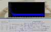
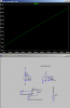
If you want to try a roll-your-own circuit without using a specialized controller IC, below is the LTspice simulation of a fairly simple constant-current hysteretic control SMPS using common IC components..
A hysteretic control SMPS has the advantage of being unconditional stable with no feedback compensation required.
The simulation shows the output current does not change (expect for the ripple) with an input step voltage change from 4V to 17V.

Note that, as with most SMPS circuits, it will not work well (or at all) if you build it on a plug-in breadboard.
It should be built on a vector board (preferably with a copper ground plane) due to the high frequency, high current signals in such a circuit.
All signal and ground paths carrying the high currents should be built with as short a connection as possible.

View attachment 121076

This might be a better option, with some modification. A LED driver using PWM control has a fixed current which is pulsing on and off. For an input source of low impedance this may prove a problem (unsure) bearing in mind the whole point of controlling the LED here is to adjust the input voltage for MPPT.

If your circuit was modified so a PWM could bias the opamp to control the current it would be analog control.
 
If your circuit was modified so a PWM could bias the opamp to control the current it would be analog control.
What is the current control range you want?
What is the PWM frequency?
How rapidly does the current set need to change?
 
Last edited:
OK I've set this up, your mission should you choose to accept it, is to drive the LED. As the input voltage rises the LED should raise current thereby placing a greater load on the input and keeping it at 6V, however, the LED current should also not raise above a particular maximum (let's say 3A).

Don't worry about current limit, PWM frequency, only starting at 6v point, for now - they are secondary to tracking the MPPT voltage.
 

Attachments

  • Screenshot_2019-10-12_22-21-03.png
    Screenshot_2019-10-12_22-21-03.png
    24 KB · Views: 166
  • mppt_experiment.asc
    1.7 KB · Views: 79
Last edited:
Sorry, but we've gone from LED constant-current drive to MPPT control, which are two entirely different things.
It would have been good if you had clearly stated up front what you wanted so I wouldn't have wasted my time on a constant-current LED circuit. :banghead:
 
They aren't entirely different, I think.

1. the MCU provides a voltage reference
2. the LED driver consumes as much current as it can while ensuring the input voltage does not fall below (1).
3. the LED driver doesn't rise above the LED emitter current limit (3A).

So you still need the constant current drive to ensure (3), perhaps it's just a case of modifying the TL431 reference a bit.
 
the MCU provides a voltage reference
From last time I did this: The MCU measure the power from the panel, increases and decreases the power looking for the best point. We constantly hunted for the best power point.
It probably does not matter if you are looking for the max power point of power from the panel or the max point of power into the battery.
There are other jobs for the MCU. Watch the battery voltage, looking for over charge point. Watch for battery short. Watch for no power from the panel.
 
1. the MCU provides a voltage reference
2. the LED driver consumes as much current as it can while ensuring the input voltage does not fall below (1).
3. the LED driver doesn't rise above the LED emitter current limit (3A).

So you still need the constant current drive to ensure (3), perhaps it's just a case of modifying the TL431 reference a bit.
You don't need the TL431 reference.
The MCU voltage reference will determine the current.

Below is the LTspice simulation of the circuit with the Vref reference input controlling the current.
The gain is 1A per volt.
The simulation is done for a Vref of 0V to 3V and supply voltages of 4V and 17V

Note: The MOSFET must be a low-threshold, logic-level device.

1570932786100.png
 
I really like constant-current hysteretic control. They are very stable.
I have had problems when the load approaches zero current.

Solar cells, with little light, produce little current. At the 4 volts point the current will be very very low.
 
I'm all over the place today but I managed to get a MPPT tracking buck working, into storage and then boosted to 5.1V.

Now I realise the solution you posted I actually need twice, for LED and USB. First of all is there off the shelf I.C's that can limit current by tracking the input voltage, settable in some way? Due to the low voltage and high efficiency requirement I'll need to replace that diode with a sync FET but I don't see it as much a problem as there's not a capacitive load. I'll be using the PIC32 comparators and vRef's I'll generate with filtered pwm

I didn't realise the .step param list would create two graphs overlaying one another. That's going to be useful in future.
 
is there off the shelf I.C's that can limit current by tracking the input voltage
A resistive divider from the input to the Vref input of my circuit would do that.
Otherwise just use the PIC.
I'll need to replace that diode with a sync FET but I don't see it as much a problem
You just have to use a non-overlap drive circuit so the two FETs are not on momentarily at the same time.
 
This is looking very nice, now with sync. :)

Couple things:

1. I was unable to work out how you overlay the step list values?
2. Any additional capacitance on the output makes it worse, though I can understand why. Is this a general feature of hysteric feedback?

Thanks again
 

Attachments

  • Screenshot_2019-10-13_16-45-36.png
    Screenshot_2019-10-13_16-45-36.png
    102.4 KB · Views: 155
I was unable to work out how you overlay the step list values?
You substitute {V} (be sure and use curlicue brackets) for the voltage value in place of the voltage value in the voltage source.
Note V1 in my simulation.
Any additional capacitance on the output makes it worse
Makes what worse?
Why do you want to add capacitance on the output?
 
Makes the ripple worse. Don't need to add capacitance, at least not for the LED. How will it fair for USB though? I imagine a lot hinges on how fast the comparator reacts?

I'm just wondering if there are any drawbacks (such as the large inductor!)

The sync in post #32 has deadtime. It's working great.
 
Screenshot_2019-10-13_19-01-15.png


I made a few changes, there's a 100k minimum load, and R5 & C1 allow for reading the current draw without another chip (INA180 etc - YAY!). I think R2 should be connected to a voltage that is unlikely to change, like vRef?
 
I mean for an actual build, the 3.3v would be used for other devices so could have some noise on it. Perhaps not enough for the comparator to be worried about though.
 
I mean for an actual build, the 3.3v would be used for other devices so could have some noise on it. Perhaps not enough for the comparator to be worried about though.
The comparator is fairly insensitive to noise on the supply voltage, but there should be a 100nF ceramic cap from the supply pin to the ground pin for high frequency noise decoupling.
 
Hi again,

I have this circuit fabricated and I'm building it today.

An area I didn't manage to resolve is the size of the inductor. I'm aware the comparator speed is going to make a big difference but still at 3A the 100u+ inductor for decent ripple performance is sizeable. Adding any capacitance on the output causes ripple to increase significantly (opposite to a buck). I can live with it for driving an LED given no capacitance is required but for limiting a USB a device will probably include it's own input capacitance resulting in this circuit exhibiting huge ripple.

Andrew
 
Last edited:
My fault, stuck the capacitance from inductor to ground which bypassed the sense. Now working perfectly with a tiny inductor. :)

At 10uH there is a 80mA current regulation delta between load, at 47uH it's 40mA
 
Status
Not open for further replies.

Latest threads

New Articles From Microcontroller Tips

Back
Top