Continue to Site

Welcome to our site!

Electro Tech is an online community (with over 170,000 members) who enjoy talking about and building electronic circuits, projects and gadgets. To participate you need to register. Registration is free. Click here to register now.

  • Welcome to our site! Electro Tech is an online community (with over 170,000 members) who enjoy talking about and building electronic circuits, projects and gadgets. To participate you need to register. Registration is free. Click here to register now.

20W Power Supply for Stereo Amplifier

ChrisETO

Member
An acquaintance M is good at the practical side of building electronic circuits, but maybe not so good on the theory, so a friend used to help him with that. The friend wasn't able to help with this circuit, and M went ahead with building it anyway.

It is a two rail power supply for a 20W stereo power amplifier. Toroidal transformer, full-wave rectifiers and capacitors. He intended to use Zener diodes with resistors to stabilise the output voltage, but didn't know how to decide on their resistance.

He asked me. It looked a bit crude to me and I was concerned that there would be a lot of power dissipated across the Zeners. It's worse than I thought. Since the transformer is 30-0-30, the output of the rectifier and capacitors will be the peak voltage of 41V and since the output should be 24V, there will be a 17V drop which will mean about 14W dissipated per rail. Not sensible.

I would replace the transformer with something more appropriate (24-0-24?), but since he has paid over £100 for the transformer, I suspect he would be reluctant to do so.

Instead of the Zeners, he could use regulator chips like LM317/LM337, I think that the chip controls the voltage without dumping it as heat, so the 17V drop wouldn't be a problem, but I'm not sure, am I correct?

No you're not, it just moves the heat to the chips instead of the resistors - and you would need MUCH bigger regulators than those, and huge heatsinks.

He NEEDS a proper transformer, something like a 15-0-15 or 16-0-16, whatever he can find round there.

The existing transformer is MASSIVELY too high, you're going to waste loads of energy as heat, and the regulators are likely to be more complicated than the amplifier is.

To be fair, we've probably all done it at some time - I've still got a transformer that a friend and I bought back in the early 70's - we went to the nearest city, which had an electronics shop, and they hadn't got the transformer we wanted, so we got the closest 'next one up' they had. We made various failed attempts with it over the years (it was for a disco/PA amplifier), but it's still sat here on a shelf - I 'think' it's 45-0-45?.
 
Linear regulators dissipate power in proportional to load current through them, * voltage drop across them.
No load, no heat.

A resistor + zener regulator has to have somewhat more than the maximum possible load current passing through the resistor all the time.

That current is then split between the zener and the actual load. All in the zener at zero load, mostly in the load when that's maxed out.

Fine for a few milliamps, but ludicrous for high currents.
 
You could use a couple of high-voltage, buck switching regulators to reduce the rectified ≈40Vdc to the desired 24Vdc with low loss (example).
This will provide a stable voltage for the amp, minimizing any distortion from fluctuations in the supply voltages.
The IC switching regulator used in that module has a switching frequency of 150kHz, so should not generate any audible interference in the amplifier output.


Edit: Changed referenced example regulator to one more appropriate.
 
Last edited:
Is that another name for a switched-mode-pwer-supply?
It is a type of switched-mode power supply which reduces a DC voltage, rather like an automobile is a type of motor-vehicle.
There are several types of switched-mode regulators, such a buck, boost, buck-boost, and line operated.
I think it would replace transformer, rectifier, smoothing and regulation.
It is not a line-operated switch-mode regulator.
So it would not replace the transformer, since it needs a low input voltage (53Vdc max.), isolated from the main's voltage.
 
Last edited:
It is a type of switched-mode power supply which reduces a DC voltage.
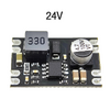
I see, so sort of half an SMPS then. It might be the answer if he won't replace the transformer and the amp can't take a higher voltage. It sounds too complicated for him to build, so I looked for a module and found
this buck-converter.
1749512910949.png
The relevant specs are:
£5.89
Input voltage: 6V~100V (input must be larger than output)
Output voltage: 5V/9V/12V/24V
Output current: 3A (maximum peak) long time current within 2A
Conversion efficiency: 96% (maximum)

Output ripple: <30mA
Output accuracy: ±0.1V
No-load current: 1mA
Operating frequency: 1MHz


I am suspicious of the "Output ripple". Would that be at the operating frequency? If so not a problem, but otherwise, I don't know.
 
Last edited:
SMPS includes all switching converters that includes;

A) acdc & dcdc ,
B) isolated & non-isolated,
C) positive & negative side load regulators.

You need one of each positive and negative dcdc ,
 
What's your definition of a "whole" SMPS
"definition" would be putting it a bit strongly, it's just my understanding of it. My computer has a power supply which contains everything to go from mains to 12V and 5V, I would call that an SMPS.

"That should work." and "Yes, it would." mean I can suggest it to M as one of three options in my order of preference. I think his would be different.
  1. Exchange the transformer for a 24-0-24 one and use 2 regulator chips.
  2. Check whether the amplifier could manage on a higher supply voltage and use 2 regulator chips.
  3. Use 2 buck-converters.
 
Last edited:
"definition" would be putting it a bit strongly, it's just my understanding of it. I have an SMPS that runs my computer which contains everything to go from mains to 12V.
So that's an SMPS that uses mains AC as input power.
The buck regulator is an SMPS that uses DC as the input power.
 
So that's...
So it's everything after the transformer and a buck regulator is a subset of SMPS that has a DC input.

Thanks, I'll let M know the options, I don't think he'll like any of them, but I don't think he has any choice. He should have got help in designing the whole circuit before spending so much money on the transformer and building the whole circuit except for the Zener bit.
 
Last edited:
Too bad the transformer is not properly sized for 20W
This would have been be a cheap dual dcdc supply solution.


But I wonder if a 30V Zener-like raw regulator could work with above with a suitable bridge and Cap size.
 
If it's supposed to be a dual supply to the amp, +V, 0V, -V you can't use two similar DC-DC buck converters.

They are non-isolated and pass (usually) the negative straight through. That's OK to reduce the positive side, but not the negative.

Also note that if you get DC-DC modules from ebay etc., most sellers don't understand what they are selling and the ratings are often confused. Get ones rated for at least twice the required load, if not 3x.
 
"20W" is not a lot of information.

Audio guys unsatisfied with off-the-shelf performance talk about "Class A" amplifiers (very inefficient heat producers compared to more modern approaches).

What speaker is he driving to get his 20w? 4, 8, 16 ohm?

Also, using the current transformer, he will ultimately only have more "headroom" in the power amplifier than he needs. Nothing wrong with that as long as his pre-amp is redesigned for +/-41v supply instead of +/-13v supply. He can set the gain appropriately and/or add a fixed resistor to the volume pot to make sure he doesn't blow his speakers. Most power transistors can handle 50v.

Note: OP amps work just fine over a broad range of power supply voltages. Same idea here. Also, he can add constant current sources to supply his input and preamp stages so he can change to nearly any supply voltage with minimal redesign effort. Look at a high quality op amp circuit for inspiration.
 
Last edited:
"definition" would be putting it a bit strongly, it's just my understanding of it. My computer has a power supply which contains everything to go from mains to 12V and 5V, I would call that an SMPS.

"That should work." and "Yes, it would." mean I can suggest it to M as one of three options in my order of preference. I think his would be different.
  1. Exchange the transformer for a 24-0-24 one and use 2 regulator chips.
  2. Check whether the amplifier could manage on a higher supply voltage and use 2 regulator chips.
  3. Use 2 buck-converters.

I refer you to my previous reply, 24-0-24 is far too high, if replacing the transformer why not get one the correct voltage?, rather than still trying to bodge a regulator solution (complete with big heatsinks etc.).

A cheaper, and easier, solution would be to replace the transformer with two cheap Chinese mains SMPSU's - you can get 24V ones, and two of those would give you 24-0-24V DC, at low cost and high efficiency. They are fairly easily to modify to different voltages as well (within reason) - I used two to create 17-0-17V to replace a missing mixer PSU.
 

Latest threads

Back
Top