Continue to Site

Welcome to our site!

Electro Tech is an online community (with over 170,000 members) who enjoy talking about and building electronic circuits, projects and gadgets. To participate you need to register. Registration is free. Click here to register now.

  • Welcome to our site! Electro Tech is an online community (with over 170,000 members) who enjoy talking about and building electronic circuits, projects and gadgets. To participate you need to register. Registration is free. Click here to register now.

2 wire LCD with a 74hc164 shift register

Status
Not open for further replies.

be80be

Well-Known Member
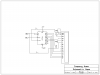
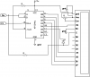
I been trying to change this to work on a 16f684 using a 74hc164 for the shift register. With no luck I was using some code that Myke Predko wrote in a book i have 123 pic microcontorller experiments.
I think the delays are not working right or it's FSR It's driving me crazy.
Code:
	list		p=16f684		; list directive to define processor
	#include	<P16F684.inc>		; processor specific variable definitions
	
	__CONFIG    _CP_OFF & _CPD_OFF & _BOD_OFF & _PWRTE_ON & _WDT_OFF & _INTRC_OSC_NOCLKOUT & _MCLRE_ON & _FCMEN_OFF & _IESO_OFF

	cblock 		0x020
	Dlay                           ;  8 Bit Delay Variable
	Temp				;  Temporary Value Used When Sending Out Data
	NOTemp				;  Temporary Value to "NybbleOutput"
	endc
#define	Data  PORTC,0
#define	Clock PORTC,1
	;  Macros
ClockStrobe MACRO		;  Strobe the Data Bit
  	bsf	 Clock
  	bcf	 Clock
 	ENDM

EStrobe MACRO			;  Strobe the "E" Bit
  	bsf	 Data
 	bcf	 Data
 	ENDM


	ORG			0x000		; processor reset vector
  	goto		init		; go to beginning of program


	ORG			0x004	    ; interrupt vector location

init:
	banksel		PORTC
	clrf		PORTC
	movlw		07h
	movwf		CMCON0
	banksel		ANSEL
	clrf		ANSEL
	banksel		TRISC
	movlw		b'00000000'
	movwf		TRISC
	banksel		PORTC	
	movlw		b'00000000'
	movwf		PORTC
	goto 		Set_LCD
Set_LCD:
	
  	call   		Dlay5                  ;  Wait 20 msecs before Reset
  	call  		Dlay5
  	call   		Dlay5
  	call   		Dlay5

  	bcf    		STATUS, C              ;  Clear Carry (Instruction Out)
  	movlw  		0x03                   ;  Reset Command
  	call   		NybbleOut              ;  Send the Nybble
  	call	 	Dlay5			;  Wait 5 msecs before Sending Again

  	EStrobe
  	call	 	Dlay160		;  Wait 160 usecs before Sending the Third Time

  	EStrobe
  	call	 	Dlay160		;  Wait 160 usecs before Sending the Third Time

  	bcf    		STATUS, C              
  	movlw  		0x02                   ;  Set 4 Bit Mode
 	call   		NybbleOut              
 	call	 	Dlay160		

  	movlw	 	0x028			;  Note that it is a 2 Line Display
  	call	 	SendINS

  	movlw	 	0x008			;  Turn off the Display
 	call	 	SendINS

  	movlw	 	0x001			;  Clear the Display RAM
  	call	 	SendINS
  	call	 	Dlay5			;  Note, Can take up to 4.1 msecs

  	movlw	 	0x006			;  Enable Cursor Move Direction
  	call	 	SendINS

  	movlw	 	0x00C			;  Turn the LCD Back On
  	call	 	SendINS

  	clrf	 	FSR			;  Output the Message
OutLoop
  	movf	 	FSR, w			;  Get the Offset to Output
  	incf	 	FSR
  	call	 	Message
  	iorlw		 0			;  At the End of the Message?
  	btfsc	 	STATUS, Z
   	goto	 	Loop			;  Yes - Equal to Zero
  	call	 	SendCHAR		;  Output the ASCII Character
  	goto	 	OutLoop

Loop				;  Loop Forever when Done
  	goto   		Loop


;  Subroutines
Message				;  Message to Output
  	addwf	 	PCL			;  Output the Characters
  	dt	 		"Hello", 0

SendCHAR			;  Send the Character to the LCD
  	movwf	 	Temp			;  Save the Temporary Value

  	swapf	 	Temp, w		;  Send the High Nybble
  	bsf	 		STATUS, C		;  RS = 1
  	call		NybbleOut

  	movf	 	Temp, w		;  Send the Low Nybble
  	bsf	 		STATUS, C
  	call	 	NybbleOut

  	return

SendINS				;  Send the Instruction to the LCD
  	movwf	 	Temp			;  Save the Temporary Value

  	swapf	 	Temp, w		;  Send the High Nybble
  	bcf	 		STATUS, C		;  RS = 0
  	call	 	NybbleOut

  	movf	 	Temp, w		;  Send the Low Nybble
  	bcf	 		STATUS, C
  	call	 	NybbleOut

  	return

NybbleOut                ; Send a Nybble to the LCD
     movwf     NOTemp    ; Save the Nybble to Shift Out
     swapf     NOTemp    ; Setup to Output to the High Part of the Byte
     movlw     6         ; Clear the Shift Register
     movwf     Dlay

NO2Loop1
     ClockStrobe
     decfsz    Dlay
     goto      NO2Loop1
     movlw     5          ; #### - Now, Shift out the Data with the "RS" Bit
     movwf     Dlay
     bsf       Data       ; Put out the Gate Bit
     ClockStrobe

NO2Loop2
     bcf       Data       ; #### - Clear the Data Bit (which is the Clock)
     btfsc     STATUS, C  ; #### - If the Bit to be output is a "1", Shift it Out
     bsf       Data               
     ClockStrobe
     rlf       NOTemp     ; #### - Shift the Next Bit into the Carry Flag
     decfsz    Dlay
     goto      NO2Loop2

     EStrobe              ; Strobe out the LCD Data

     return

Dlay160                         ;  Delay 160 usecs

  	movlw  		256 - ( 160 / 4 )      ;  Loop Until Carry Set
  	addlw  		1
  	btfss  		STATUS, C
   	goto  		$-2

  	return

Dlay5                           ;  Delay 5 msecs

  	movlw  		4                      ;  Set up the Delay
  	movwf  		Dlay
  	movlw  		256 - 0x0E8
  	addlw  		1
  	btfsc  		STATUS, Z
   	decfsz		Dlay
    goto	 	$-3

  	return


  end
Thanks for any help


See i get this when I build the line it points to is the delay
Warning[202] C:\2WIRE\2WIRE1.ASM 163 : Argument out of range. Least significant bits used.
Warning[202] C:\2WIRE\2WIRE1.ASM 174 : Argument out of range. Least significant bits used.
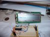
Oh one more thing the lcd comes on and rolls out 8 squares
 

Attachments

  • lcdshift.PNG
    lcdshift.PNG
    7.8 KB · Views: 1,909
Last edited:
Oh man i wish this was in C lol if it was i would be able to help more.

1 question.... can you test the shift registers output to ensure the pins are shifting.


It seems to be a delay issue tho. Try creating your own delays and see what happens.

Why use: 256 - ( 160 / 4 )
why not just use:

216

also why: 256 - 0x0E8
why 0x0E8 ? its the same as 0xE8 and in fact just use:

24

try it with those stable values and see if it helps
 
I found one for sure error I missed a pin on the 74hc164.
That sure didn't help.
I'm going to fix that first
 
I had changed the delay It was where I missed the wire LOL it's alive
 

Attachments

  • LCDshift.JPG
    LCDshift.JPG
    104.8 KB · Views: 1,167
What happen is I missed Q4 on the 74hc and put RS on Q5. That's why i want to start using PCB for my boards. To many jumper for things like this.
Your delay numbers worked the code as posted worked and the delays i got from here work
 
Similar problem but connections are fine:

I have a similar problem, using the code listed above, but changed for use with the PIC16F88. I have the 74HC164 connected to the PIC and HD44780 LCD screen as in the schematic that is the same as listed earlier (also attached).

The code compiles fine and runs in the MPLAB SIM fine but the output to the 2x16 LCD screen is more or less random characters displayed on the 2 rows. If power is taken away and re-applied the same thing happens with different characters located in different locations on the screen.

I can't figure out what is wrong. Searching for a 2 Wire Interface has turned up very little with the 16F88. If you see what I'm missing I'd really appreciate the help.

Code:
	List		P=16F88		; List directive to define processor
	#Include	<P16F88.inc>	; Processor specific variable definitions

	__CONFIG	_CONFIG1, _PWRTE_ON  & _WDT_OFF & _INTRC_IO & _BODEN_OFF & _LVP_OFF & _CP_OFF & _MCLR_OFF
	__CONFIG	_CONFIG2, _IESO_OFF & _FCMEN_OFF

	Cblock 		0x020
	Dlay				; 8 Bit Delay Variable
	Temp				; Temporary Value Used When Sending Out Data
	NOTemp				; Temporary Value to "NybbleOutput"
	endc

#Define	Data  PORTA,0
#Define	Clock PORTA,1

	; Macros

ClockStrobe MACRO		; Strobe the Data Bit
	bsf	Clock
	bcf	Clock
	ENDM

EStrobe MACRO			; Strobe the "E" Bit
  	bsf	Data
 	bcf	Data
 	ENDM

	ORG	0x00		; Processor Reset Vector
  	goto	START		; Go to beginning of program


	ORG	0x04		; Interrupt Vector Location

START
	CLRF	PORTA		; PortA all low
	CLRF	PORTB		; PortB all low
	BSF	STATUS,RP0	; Bank 1
	MOVLW	b'01100000'	; Make clock 4Mhz
	IORWF	OSCCON
	MOVLW	b'00100000'	; Bit 5 input
	MOVWF	TRISA		; PortA all output except MCLR
	CLRF	TRISB		; PortB all output
	CLRF 	ANSEL		; Make PORTA all digital I/O
	BCF	STATUS,RP0	; Bank 0

; ===== Initialize LCD =====
	
	call	Dlay5		; Wait 20 msecs before Reset
	call	Dlay5
	call	Dlay5
	call	Dlay5

	bcf	STATUS, C	; Clear Carry (Instruction Out)
	movlw	0x03		; Reset Command
	call	NybbleOut	; Send the Nybble
	call	Dlay5		; Wait 5 msecs before Sending Again

	EStrobe
	call	Dlay160		; Wait 160 usecs before Sending the Third Time

	EStrobe
	call	Dlay160		; Wait 160 usecs before Sending the Third Time

	bcf	STATUS, C
	movlw	0x02		; Set 4 Bit Mode
	call	NybbleOut
	call	Dlay160

	movlw	0x28		; Note that it is a 2 Line Display
	call	SendINS

	movlw	0x08		; Turn off the Display
	call	SendINS

	movlw	0x01		; Clear the Display RAM
	call	SendINS
	call	Dlay5		; Note, Can take up to 4.1 msecs

	movlw	0x06		; Enable Cursor Move Direction
	call	SendINS

	movlw	0x0C		; Turn the LCD Back On
	call	SendINS

	clrf	FSR		; Output the Message

OutLoop
	movf	FSR, w		; Get the Offset to Output
	incf	FSR
	call	Message
	iorlw	0		; At the End of the Message?
	btfsc	STATUS, Z
	goto	Loop		; Yes - Equal to Zero
	call	SendCHAR	; Output the ASCII Character
	goto	OutLoop

Loop				;  Loop Forever when Done
  	goto   		Loop


; ===== Subroutines =====
Message				; Message to Output
	addwf	PCL		; Output the Characters
	dt	"Hello", 0

SendCHAR			; Send the Character to the LCD
  	movwf	Temp		; Save the Temporary Value

	swapf	Temp, w		; Send the High Nybble
	bsf	STATUS, C	; RS = 1
	call	NybbleOut

	movf	Temp, w		; Send the Low Nybble
	bsf	STATUS, C
	call	NybbleOut

	return

SendINS				; Send the Instruction to the LCD
	movwf	Temp		; Save the Temporary Value

	swapf	Temp, w		; Send the High Nybble
	bcf	STATUS, C	; RS = 0
	call	NybbleOut

	movf	Temp, w		; Send the Low Nybble
	bcf	STATUS, C
	call	NybbleOut

	return

NybbleOut			; Send a Nybble to the LCD
	movwf	NOTemp		; Save the Nybble to Shift Out
	swapf	NOTemp		; Setup to Output to the High Part of the Byte
	movlw	6		; Clear the Shift Register
	movwf	Dlay

NO2Loop1
	ClockStrobe
	decfsz	Dlay
	goto	NO2Loop1
	movlw	5		; #### - Now, Shift out the Data with the "RS" Bit
	movwf	Dlay
	bsf	Data		; Put out the Gate Bit
	ClockStrobe

NO2Loop2
	bcf	Data		; #### - Clear the Data Bit (which is the Clock)
	btfsc	STATUS, C	; #### - If the Bit to be output is a "1", Shift it Out
	bsf	Data
	ClockStrobe
	rlf	NOTemp		; #### - Shift the Next Bit into the Carry Flag
	decfsz	Dlay
	goto	NO2Loop2

	EStrobe			; Strobe out the LCD Data

	return

Dlay160				; Delay 160 usecs

	movlw	216		; Loop Until Carry Set
	addlw	1
	btfss	STATUS, C
	goto	$-2

	return

Dlay5				; Delay 5 msecs

	movlw	4		; Set up the Delay
	movwf	Dlay
	movlw	24
	addlw	1
	btfsc	STATUS, Z
	decfsz	Dlay
	got0	$-3

	return

  end
 

Attachments

  • lcdshift.PNG
    lcdshift.PNG
    4.6 KB · Views: 1,247
your code looks ok but i would use this to set digital
Code:
BANKSEL ANSEL ; Select Bank of ANSEL
MOVLW 0x00 ; Configure all pins
MOVWF ANSEL ; as digital inputs
 
I tried adding your suggestion to add three commands to my configuration commands, though I thought it would do the exact same as "CLRF ANSEL".

It resulted in nothing different. I still think that the problem is in the commands that set-up and sending the data to the 74HC164 shift register itself. Any more ideas? I might just try doing this using PORT B instead of PORT A, though I'm wondering if this will make any difference at all.
 
Try this and see if it don't work
Code:
  list		p=16f88		; list directive to define processor
	#include	<P16F88.inc>		; processor specific variable definitions
	
 __CONFIG    _CONFIG1, _CP_OFF & _CCP1_RB0 & _DEBUG_OFF & _WRT_PROTECT_OFF & _CPD_OFF & _LVP_OFF & _BODEN_OFF & _MCLR_ON & _PWRTE_ON & _WDT_OFF & _INTRC_IO
     __CONFIG    _CONFIG2, _IESO_OFF & _FCMEN_OFF
	cblock 		0x020
	Dlay                           ;  8 Bit Delay Variable
	Temp				;  Temporary Value Used When Sending Out Data
	NOTemp				;  Temporary Value to "NybbleOutput"
	endc
#define	Data  PORTA,0
#define	Clock PORTA,1
	;  Macros
ClockStrobe MACRO		;  Strobe the Data Bit
  	bsf	 Clock
  	bcf	 Clock
 	ENDM

EStrobe MACRO			;  Strobe the "E" Bit
  	bsf	 Data
 	bcf	 Data
 	ENDM


	ORG			0x000		; processor reset vector
  	goto		init		; go to beginning of program


	ORG			0x004	    ; interrupt vector location

init:
	banksel 	OSCCON	
	movlw       b'01100000'
	movwf 		OSCCON
	banksel		PORTA
	clrf		PORTA
	banksel		ANSEL
	clrf		ANSEL
	banksel		TRISA
	movlw		b'00000000'
	movwf		TRISA
	banksel		PORTA	
	movlw		b'00000000'
	movwf		PORTA
	goto 		Set_LCD
Set_LCD:
	
  	call   		Dlay5                  ;  Wait 20 msecs before Reset
  	call  		Dlay5
  	call   		Dlay5
  	call   		Dlay5

  	bcf    		STATUS, C              ;  Clear Carry (Instruction Out)
  	movlw  		0x03                   ;  Reset Command
  	call   		NybbleOut              ;  Send the Nybble
  	call	 	Dlay5			;  Wait 5 msecs before Sending Again

  	EStrobe
  	call	 	Dlay160		;  Wait 160 usecs before Sending the Third Time

  	EStrobe
  	call	 	Dlay160		;  Wait 160 usecs before Sending the Third Time

  	bcf    		STATUS, C              
  	movlw  		0x02                   ;  Set 4 Bit Mode
 	call   		NybbleOut              
 	call	 	Dlay160		

  	movlw	 	0x028			;  Note that it is a 2 Line Display
  	call	 	SendINS

  	movlw	 	0x008			;  Turn off the Display
 	call	 	SendINS

  	movlw	 	0x001			;  Clear the Display RAM
  	call	 	SendINS
  	call	 	Dlay5			;  Note, Can take up to 4.1 msecs

  	movlw	 	0x006			;  Enable Cursor Move Direction
  	call	 	SendINS

  	movlw	 	0x00C			;  Turn the LCD Back On
  	call	 	SendINS

  	clrf	 	FSR			;  Output the Message
OutLoop
  	movf	 	FSR, w			;  Get the Offset to Output
  	incf	 	FSR
  	call	 	Message
  	iorlw		 0			;  At the End of the Message?
  	btfsc	 	STATUS, Z
   	goto	 	Loop			;  Yes - Equal to Zero
  	call	 	SendCHAR		;  Output the ASCII Character
  	goto	 	OutLoop

Loop				;  Loop Forever when Done
  	goto   		Loop


;  Subroutines
Message				;  Message to Output
  	addwf	 	PCL			;  Output the Characters
  	dt	 		"Hello", 0

SendCHAR			;  Send the Character to the LCD
  	movwf	 	Temp			;  Save the Temporary Value

  	swapf	 	Temp, w		;  Send the High Nybble
  	bsf	 		STATUS, C		;  RS = 1
  	call		NybbleOut

  	movf	 	Temp, w		;  Send the Low Nybble
  	bsf	 		STATUS, C
  	call	 	NybbleOut

  	return

SendINS				;  Send the Instruction to the LCD
  	movwf	 	Temp			;  Save the Temporary Value

  	swapf	 	Temp, w		;  Send the High Nybble
  	bcf	 		STATUS, C		;  RS = 0
  	call	 	NybbleOut

  	movf	 	Temp, w		;  Send the Low Nybble
  	bcf	 		STATUS, C
  	call	 	NybbleOut

  	return

NybbleOut                ; Send a Nybble to the LCD
     movwf     NOTemp    ; Save the Nybble to Shift Out
     swapf     NOTemp    ; Setup to Output to the High Part of the Byte
     movlw     6         ; Clear the Shift Register
     movwf     Dlay

NO2Loop1
     ClockStrobe
     decfsz    Dlay
     goto      NO2Loop1
     movlw     5          ; #### - Now, Shift out the Data with the "RS" Bit
     movwf     Dlay
     bsf       Data       ; Put out the Gate Bit
     ClockStrobe

NO2Loop2
     bcf       Data       ; #### - Clear the Data Bit (which is the Clock)
     btfsc     STATUS, C  ; #### - If the Bit to be output is a "1", Shift it Out
     bsf       Data               
     ClockStrobe
     rlf       NOTemp     ; #### - Shift the Next Bit into the Carry Flag
     decfsz    Dlay
     goto      NO2Loop2

     EStrobe              ; Strobe out the LCD Data

     return

Dlay160                         ;  Delay 160 usecs

  	movlw  		256 - ( 160 / 4 )      ;  Loop Until Carry Set
  	addlw  		1
  	btfss  		STATUS, C
   	goto  		$-2

  	return

Dlay5                           ;  Delay 5 msecs

  	movlw  		4                      ;  Set up the Delay
  	movwf  		Dlay
  	movlw  		256 - 0x0E8
  	addlw  		1
  	btfsc  		STATUS, Z
   	decfsz		Dlay
    goto	 	$-3

  	return


  end
 
Thanks Burt! They worked, looking more closely at my circuit I noticed that the diode was inserted backwards. Now works like a charm :)
 
Status
Not open for further replies.

Latest threads

New Articles From Microcontroller Tips

Back
Top