Continue to Site

Welcome to our site!

Electro Tech is an online community (with over 170,000 members) who enjoy talking about and building electronic circuits, projects and gadgets. To participate you need to register. Registration is free. Click here to register now.

  • Welcome to our site! Electro Tech is an online community (with over 170,000 members) who enjoy talking about and building electronic circuits, projects and gadgets. To participate you need to register. Registration is free. Click here to register now.

18 Channel RGB (54 LED) Color Wave Using PIC16F628A

Status
Not open for further replies.

Chipwizard

New Member
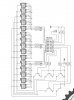
Here is an expansion of a recent design of 15 channel RGB color wave.
Use of all PIC16F628A outputs as a stand-alone system to drive 18 RGB LED's.
 

Attachments

  • AURORA 18 - Schematics.pdf
    26.1 KB · Views: 296
  • AURORA 18 - Silk.pdf
    15 KB · Views: 281
  • AURORA 18 - Top.pdf
    18.6 KB · Views: 300
  • AURORA 18 - Bottom.pdf
    23.8 KB · Views: 243
What are the results of your 15 RGB project, or your 12 RGB and 9 RGB projects for that matter? Are you simply showing us your schematic and board design capabilities?

In your 15 RGB project video, the large and abrupt color changes in the "wave" suggest you may only have a few bits color resolution per LED and/or a very low refresh rate. Do you have any meaningful software specifications to share for any of these projects?
 
Last edited:
What kind of results are you looking for Mike? Everything you need for 15 RGB is on the page. You have color mapping, source code mapping, you have resolution, PCB layout, and schematics. You already know it works. So all you have to do is build the circuit and write your code based on the model.
Regards,
Rom
 
Hi Rom,

I'm just trying to figure out your motivation for posting version after version of an RGB color wave project. Please correct me if I'm wrong but it seems your purpose is;

(1) To show off your creative schematic design.
(2) To show off your creative PCB design.

Without software, less experienced users can't duplicate the project so it seems you're just showing off, right?

I apologize for the criticism. Obviously I'm not your intended audience. Your hardware design is ok (Multiplexing 101) but I like to study software to see how the pwm resolution, color depth, refresh rate, and special effects were achieved.
 
Last edited:
Mike:
The purpose is neither mentioned above. Creative PCB design and schematics are just means to the goal.
The intended goal is to provide audience with interest and excitement to learn more about capabilities of PIC and think outside the box creating their own code and color FX. This concept is not just limited to moving a rainbow of colors across the screen. One can expand on the idea. For me it was a fun project and a challenge to see if I can do it. My application will be in landscape lighting and lighting up motor cycles.
The objective: To create a stand-alone system driving 15 RGB LED's
General Specifications:
System to run on 2-wire power supply
Direct drive of RGB LED's with minimum required parts and low cost
No use of registers/latches to drive the LED's, or a computer to run the program
Create color effects at will by changing the code without changing the hardware layout
Have the highest brightness and vividness of colors without flickering given limited programming space on the controller

Intended audience: One who has knowledge of working with and programming a microcontroller, knowledge of reading and understanding schematics, knowledge of building a double sided pcb and soldering based on pcb layout provided. By all means this is not a beginer's project who is just learning about electronics and more specifically microcontrollers.
 
Last edited:
Source Code Layout Implementation

Although I will not post a code I will do my best to describe how the programming concept works. Attached please find schematic layout and programming code guide for the 15 RGB version to follow.

Program Setup Concept
1- Since there are 15 RGB's, the program uses only 15 colors. This allows colors to remain vivid.
2- To minimize the code lines to fit the chip I had to make a compromise on resolution (Again maximum colors needed are only 15). 3-Bit resolution format per primary color, repeated 15 times.
3- To prevent flickering I had to maintain the refresh rate constant (100)
4- To compensate for 20% duty cycle (compromising the brightness), LED's are slightly over driven for a very short time by reducing resistor values. Parallel to that software refreshes at an even higher rate and maintains the high state for a bit longer time.
 

Attachments

  • AURORA15-SCHEMATICS (2).jpg
    AURORA15-SCHEMATICS (2).jpg
    105.6 KB · Views: 327
  • Aurura15 - Data Map.pdf
    8.6 KB · Views: 283
Last edited:
Decoding the Program for 15 RGB
The program creates it's own PWM without use of internal PWM of the PIC.
There are 15 RGB or total of 45 bits that needs to be addressed at each pass thru.
A) PWM and color coding is sulmultaneously achieved by creating 15 "Groups" (15 main subroutines). Each "Group" creates one frame of motion picture. Each Group is looped 15 times for motion smoothness. With 15 Frames you can make the movie. Each Frame places one specific color set across all 15 RGB. Next frame moves the same color set over one RGB and so on until the 15th RGB on the 15th frame will have same color as the 1st RGB on the 1st Frame.
B) Each Group calls 5 "Sections" (multiplex 5 you see in schematics) to set the colors on 15 RGB. There are 15 x 5 = 75 Sections called in the program for the entire movie.
Eah section loops 100 times to refresh the color and to prevent flickering. Each section has 3 pair sets of color command. PortB1, PortA1...PortB2, PortA2,...PortB3, PortA3 (Resolution 3) setting and maintaining colors.
C) At the same time that colors are called (8 bits of PortB, plus bits A0 of PortA), bits of A1, A2, A3, A6, A7 are set one at a time to indicate which of 5 sections are addressed completing the multiplexing.
Section 1 sets colors for RGB1, RGB6, RGB11, Section 2 sets colors for RGB2, RGB7, RGB12.......and Section 5 sets the colors for RGB5, RGB10, RGB15.
D) After one entire frame is completed, 5 sections are called and 15 LED's have been addressed. Next frame will change the color code in PortB+A0 and calls 5 more sections and so on...

I did try the system with 4 bit resolution (Calling 4 pair sets of color commands) and I simply ran out code space. (Addtional 6 lines per section x 75 sections) But that does not make a difference as the resolution sets the color and not the transitions between frames.
 
Last edited:
If one wants to smooth out the transitions between frames, I suggest to fade each 15 "Group" calls. I believe there is enough programming space to make this happen. If I have time I will toy with it and post. Remember each group call produces a single frame.
 
Last edited:
Here is a heads up that demistifies RGB9, RGB12, RGB15. Once you figure out the programming logic you can easily and quickly expand from 9 to 15 RGB.
All of the above use 9 bits (All PortB plus A0 bit) as base color generation. The difference is number of multiplex bits used in hardware and number of sections called in software.
Example:
RGB9 uses A1, A2, A3 as multiplex bits with proper resistors and sinking transistors. 9 colors across 9 RGB moved 9 positions. Program calls 3x3x3 =27 sections. 33.3% duty cycle.
RGB12 uses A1,A2,A3,A6 as multiplex bits. 12 colors across 12 RGB moved 12 positions. Program calls 3x4x4 =48 sections. 25% duty cycle.
RGB15 uses A1,A2, A3, A6, A7 as multiplex bits, Program calls 3x5x5 =75 sections. 20% duty cycle.
RGB9,12,15 use max 3 bit resolution to achieve the colors.
As you can see by increasing the multiplexing bits by one, you increase number of RGB by 3, and number of line codes required increases exponentially.
 
Last edited:
Mike
I would not call that critism but rather an insult. Although I do not believe you have any interest in building and experimenting with the project, I hope the description of the project I provided helps you and other audience understanding it better. Best of luck, happy experimenting.
Regards,
Rom
 
... I hope the description of the project I provided helps you and other audience understanding it better ...

Hi Rom,

You've done a nice job extending the hardware of Pete's original design (27 channel PWM on a 16F88). Keep up the good work. I'm sure someone will get something out of it.

Please let us know if you need help with software? I've got a BAM (bit angle modulation) demo (209 words) for Pete's original 3x9 project that provides ultra fine 2-usec duty cycle steps and 8-bit (256 level) resolution per LED with a 651-Hz refresh rate. You would only need to modify a few lines of code to drive a 4x9 (36 LED) matrix at 488-Hz or a 5x9 (45 LED) matrix at 390-Hz (8-MHz 16F88).

Regards, Mike
 
Last edited:
Hi Rom,

You've done a nice job extending the hardware of Pete's original design (27 channel PWM on a 16F88). Keep up the good work. I'm sure someone will get something out of it.

Thanks for the compliment.

Please let us know if you need help with software? I've got a BAM (bit angle modulation) demo (209 words) for Pete's original 3x9 project that provides ultra fine 2-usec duty cycle steps and 8-bit (256 level) resolution per LED with a 651-Hz refresh rate. You would only need to modify a few lines of code to drive a 4x9 (36 LED) matrix at 488-Hz or a 5x9 (45 LED) matrix at 390-Hz (8-MHz 16F88).

I would be interested to know if you used a table lookup for data generation (like Pete did) or you used a direct programming approach. I am converting mine to a data table lookup so that I can create different affects running the same main program. I would eventually like to expand further to data transfer from an external EEPROM for contineous affects for a long period of time. (Hours)

Regards,
Rom
 
Last edited:
Status
Not open for further replies.

Latest threads

New Articles From Microcontroller Tips

Back
Top