Continue to Site

Welcome to our site!

Electro Tech is an online community (with over 170,000 members) who enjoy talking about and building electronic circuits, projects and gadgets. To participate you need to register. Registration is free. Click here to register now.

  • Welcome to our site! Electro Tech is an online community (with over 170,000 members) who enjoy talking about and building electronic circuits, projects and gadgets. To participate you need to register. Registration is free. Click here to register now.

16F88 Interrupt Problem

Status
Not open for further replies.

jerryd

New Member
Electro Tech forum,

I can't figure out the problem with the attached circuit.
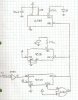
Sorry about the drawing I don't have a schematic program.

4050 is a buffer
4040 is a 12 bit ripple counter
4518 is a decade counter
16F88 is a pic

All the circuit does is divide the 60HZ by 512 and the reset
is used to clock the 4518 and Q1 blinks the led. This works
fine.

Then I use the reset as an external interrupt for the 16F88.
Doesn't work. BUT! if I just wire pin 11 of the 4518 to
the interrupt pin(RB5) the 16F88 diode blinks according to
my program.

I can't seem to trigger on this reset with my analog scope.
I tried wiring the reset through a buffer but it didn't help.

jerryd
 

Attachments

  • interrupt0001.jpg
    interrupt0001.jpg
    1.3 MB · Views: 240
I'm guessing that the pulse is too short to trigger the interrupt. It could also depend on your code as by the time the interrupt is executed the pin will be back to zero. Why don't you feed the 60Hz straight into the pic and count internally?

Mike.
 
Pommie,

Thanks for the reply.

Good question. I have done this on other circuits and it
works great even without the buffer because RB0 is Schmitt
trigger input.

Here I'm using the 60HZ as a time base for a propellor clock
but I'm also using another interrupt from an IR receiver to
start the led display routine. When the display routine gets
interrupted by the 60HZ interrupt it looses it's place and the
digits jump around. My aim here was to only interrupt the
display routine once a minute and see if it looks better.

I've never made a propellor clock before so my approace may
be wrong.

jerryd
 
How often is your diplay routine running? How many digits? The 60Hz interrupt is so slow that it shouldn't affect your display at all.

I have a tach program on a breadboard right now using a 4 digit display. I have the display routine running at ~500Hz. At each entry it updates one digit. The display never flickers even though the signal it reads is well over 60Hz.
 
upand-at-them,

The display routine is started 50 ms after the IR
transition. The motor makes 1 rotatation every 100ms
or 600rpm. Four digits are displayed during 1 revolution.

Here's the code(basic) to display 1 digit:

'procedure to display one digit
sub procedure timeDisplay
for x = 0 to 4
PORTA = bits[n][x]
delay_us(50) 'leave LEDs on for 50us
PORTA = %00000000 'turn off the LEDs
delay_us(150) 'space between LED columns
next x
end sub

I call this 4 times with 450us between the first 2 digits
and 1ms between them and the next 2 digits. So the whole
routine takes about 5ms. Works OK except for the interrupt
problem.

Can you suggest a better way? The motor is voltage controlled
so I can change the speed.

jerryd
 
Feed the 60Hz signal into the timer0 pin and use the timer to count pulses. At the end of each revolution read the timer and calculate the number of pulses received by subtracting the previous reading, add this to your 60Hz counter. Never zero the timer as you might lose a pulse.

something like,
Code:
    new=timer0
    count=previous-new
    time60=time60+count
    previous=new
    if time60>60 then
        time60=time60-60
        seconds=seconds+1
        if seconds>60 ....
        ....etc
    endif

Edit, an afterthought, feed 60Hz into B6 and use timer1 with the ccp module special events trigger to automatically zero itself at 60 and then CCP1IF will get set every second. A bit like magic.

Mike.
 
Last edited:
Pommie,

I think I understand your first suggestion about using
timer0. Pin RA4 is spoken for so I would have to use
timer1(RB6).

Reading the datasheet it looks like I would have to set
the T1CON register to %00000011

Using it as a pulse counter I can read it's value every
rotation and do the math but at some point the counter
will roll over.

In that case I could find the timer1 counter value to be
less than the last time I read it so I would have to subtract
the old timer1 counter value from 65536 and add the new timer1
value to the answer.

ex:
I read it and it's 65532. The next time I read it it's 2.
So (65536 - 65532) = 4 + the 2 = 6 pulses counted.

Does that make sense?


I don't understand the "ccp module special events trigger"
at all. I read the datesheet but didn't get it.

Thanks for the help so far.
jerryd
 
If you're updating the 4 digits every 100ms, that's only 10Hz. The flicker would be obvious even without a signal interrupt. I would setup a timer with a frequency that is a multiple of 60Hz, like 480Hz. And setup the signal to trigger an external interrupt and increment a counter. On every timer interrupt you update one display digit and then mark the next one to be updated. On every 8th timer interrupt you move the counter value into the display latch and then clear the counter. Or did I misunderstand your project?
 
Hi Jerry,

If you set the registers to,
Code:
	T1CON=3
	CCP1CON=11
	CCPR1L=60
	CCPR1H=0
	TMR1L=0
	TMR1H=0
Then timer1 will automatically reset after 60 counts and the bit CCP1IF in PIR1 will get set. So in your code you can do,
Code:
    if PIR1.CCP1IF=1 then
        PIR1.CCP1IF=0
        seconds=seconds+1
        if seconds=60 then
              minutes ......
        endif
    endif

Mike.
 
Last edited:
upand_at_them,

Since my project is a propellor clock the leds are only in
the correct place for a small part of the 10HZ rotation
speed of the motor. In the attached photo I happen to
be displaying all the digits.

If I don't update them all on every rotation won't I have
a persistance problem?

jerryd
 
Pommie,

Thanks, I'll read about those bits.

It's getting late here in Florida so I'll get back
tomorrow.

jerryd
 
upand_at_them,

Forgot to attach the photo.
Here it is.

jerryd
 

Attachments

  • P1010177.JPG
    P1010177.JPG
    883.9 KB · Views: 165
Pommie,

I think I understand the capture and compare feature now.

I breadboarded it but can't get it to work. All the breadboard
has is a 470ohm resistor and an led going to ground on PORTA.0.
PORTA doesn't toggle at all, I must be missing something.

I can get it to work if I hang my scope probe on RB6. Otherwise
PORTA.0 is always high.

Probe specs are:
Attenuation: 1X / 10X
Input resistance: 1M / 10M
Input capacitance: 1*85pF-120pF

It shouldn't need a pullup since the 60HZ is comming off a CMOS
buffer and it's a nice 5V square wave.

I have external interrupts enabled, maybe that's a problem.

I notice in my project menu CCP1 is assigned to RB0.

Any suggestions?

If I can get this working it's exactly what I need.

jerryd
 
Pommie,

Update!

I can get it to work without the probe if I add a 0.001uf cap to
ground on RB6. Without the cap PORTA.0 is always high.

Confused.

jerryd
 
Status
Not open for further replies.

Latest threads

New Articles From Microcontroller Tips

Back
Top