Continue to Site

Welcome to our site!

Electro Tech is an online community (with over 170,000 members) who enjoy talking about and building electronic circuits, projects and gadgets. To participate you need to register. Registration is free. Click here to register now.

  • Welcome to our site! Electro Tech is an online community (with over 170,000 members) who enjoy talking about and building electronic circuits, projects and gadgets. To participate you need to register. Registration is free. Click here to register now.

16F84a code to 16F628a code

Status
Not open for further replies.

JKF1000

New Member
First of all, I know it is a well documented subject, but I have now spent many hours trying to find out what changes I need to make to my 16F84A code, to make it compatible with a newer 16F628A, and am now a little confused by all the different sources of information, I have searched for the migration document that Nigel mentions in a lot of his posts with no luck, I am very new to PIC programming, and not confident in what changes need to be made,

I would also like to enable the internal oscillator to save on external components, and to add higher accuracy than when using a external resonator. I have the assember code, and understand that I need to add a couple of extra lines of text.
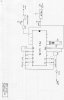
I can upload the text file if this helps, the circuit is for a very simple CTCSS tone generator.

Many thanks in advance, Karl.
 
The only changes I can think of are to the configuration line for the internal oscillator, and add the lines 'movlw 7', 'movwf CMCON' to disable the comparators to allow use of the digital pins.
 
Last edited:
The other main change is the user memory (SFRs) starts at 0x20 instead of 0x0c. There are also differences in the peripherals but these are not really a problem unless the code uses the EEPROM.

Mike.
 
Thanks for the suggestions so far, I have attached the origional code, Karl
 

Attachments

  • CTCSS.ASM
    7.8 KB · Views: 650
A quick play and I think this should work,
Code:
		#include "p16F628a.inc" 		; This includes PIC16F628 definitions for the MPASM assembler
		__config _CP_OFF & _WDT_OFF & _PWRTE_ON & _XT_OSC

		title	"CTCSS Encoder v1.4 for 16c84 Tony Hunt VK5AH"
; 14-4-99
;	Assemble with MPASM  
;   See below for wiring details  
;
		;list	P=16C84
		;__config 3FF9H		;XTAL OSC @4Mhz,NO WATCHDOG,PWRRST,NO CP.
		;__idlocs 1234
		errorlevel -302
;
CNT1		equ	20H		;PRESCALLER COUNTER REG 1
CNT2		equ	21H		;PRESCALLER COUNTER REG 2
CNT3		equ	22H		;PRESCALLER COUNTER REG 3
TONREG		equ	23H		;REGISTER FOR TONE NUMBER
PRES1		equ	24H		;PRESCALLER STORE 1
PRES2		equ	25H		;PRESCALLER STORE 2
PRES3		equ	26H		;PRESCALLER STORE 3

OPTREG		equ	OPTION_REG;	81H
PC		equ	PCL;		2
PULLUP		equ	7
OUT		equ	2
PTT		equ	7

		goto	START

		org	0100		;move to make room for extra code
START		bsf	STATUS,RP0	;SELECT REG BANK 1
		bsf	TRISB,PTT	;SETUP RB7 AS INPUT FOR PTT
		bcf	TRISA,OUT	;SETUP RA2 AS OUTPUT FOR TONE
		bcf	OPTREG,PULLUP	;SET PULLUP RESISTORS ON PORTB
		movlw	0xFF		; SET PORTB AS I/Ps
		movwf	TRISB		; RB0-RB5 FOR SWITCH INPUTS
;
		movlw	0x07		;turn off comparators
		movwf	CMCON

		bcf	STATUS,RP0	;SELECT REG BANK 0
		bcf	INTCON,GIE	;DISABLE GIE INTERUPTS
		bsf	INTCON,RBIE	;ENABLE PORT B CHANGE INTERUPT
		movf	TRISB,W		;READ DIP SWITCHES INTO W
		movwf	TONREG		;STORE IN 0F REG
		bcf	TONREG,6	; CLEAR BITS 6&7 AS
		bcf	TONREG,7	; THEY ARE IRRELAVANTS
		movf	TONREG,W	;RE-STORE INTO W
		addwf	TONREG,F	; MULTIPLY BY 3
		addwf	TONREG,F	; FOR TONE TABLE OFFSET
;
		movf	TONREG,W	;RELOAD TO W FOR OFFSET
		call	TONTBL		;GOTO TONE LOOKUP TABLE
		movwf	PRES1		;STORE FIRST VALUE FROM TABLE
;
		incf	TONREG,F	;INCREMENT FOR NEXT TABLE VALUE
		movf	TONREG,W	;RELOAD W FOR OFFSET
		call	TONTBL		;GOTO TONE LOOKUP TABLE
		movwf	PRES2		;STORE SECOND VALUE FROM TABLE
;
		incf	TONREG,F	;INCREMENT FOR NEXT TABLE VALUE
		movf	TONREG,W	;RELOAD W FOR OFFSET
		call	TONTBL		;GOTO TONE LOOKUP TABLE
		movwf	PRES3		;STORE THIRD VALUE FROM TABLE
;
;
RELOAD
		movf	PRES1,W		;LOAD W WITH PRESET FOR 1
		movwf	CNT1		;PRELOAD PRESCALLER 1
		movf	PRES2,W		;LOAD W WITH PRESET FOR 3
		movwf	CNT3		;PRELOAD PRESCALLER 3
		movf	PRES3,W		;LOAD W WITH PRESET FOR 2 READY
PTTCHK
		btfsc	PORTB,PTT	;TEST PTT LINE
		goto	WAIT		;SLEEP TILL LOW
		call	CHORUS		;DO DIVIDER/PRESCALLER ROUTINE
;
OUTPUT
		btfss	PORTA,OUT	;TEST O/P HI OR LO AT PRESENT
		goto	HI		;IF LO GO SET HI
		goto	LO		;IF HI GO SET LO
;
HI
		nop			;BALANCE OUT CYCLE TIME MARK&SPACE
		bsf	PORTA,OUT	;MAKE O/P HI
		goto	RELOAD		;RETURN TO START OF CYCLE
;
LO
		bcf	PORTA,OUT	;MAKE O/P LO
		goto	RELOAD		;RETURN TO START OF CYCLE
;
CHORUS
PRE1
		decfsz	CNT1,F		;DECREMENT PRESCALLER 1
		goto	PRE2
		goto	FINE		;CALL FINE ADJUST SUBROUTINE
PRE2		movwf	CNT2		;RELOAD PRESCALLER 2
;
PREE		decfsz	CNT2,F		;DECREMENT PRESCALLER 2
		goto	PREE		;GO BACK AND DECREMENT PRE2 TILL 00
;
		goto	PRE1		;GO BACK AND DECREMENT PRE1 TILL 00
;
FINE		decfsz	CNT3,F		;DECREMENT PRESCALLER 3
		goto	FINE		;GO BACK AND DECREMENT PRE3 TILL 00
		return			;RETURN TO CHANGE O/P AND CHECK PTT ETC
;
WAIT			 
		bcf	INTCON,RBIF	;CLEAR PORT B CHANGE INT FLAG
		sleep			;SLEEP AND WAIT FOR PTT
		nop
		bcf	INTCON,GIE	;DISABLE GLOBAL INTERUPTS AGAIN 
		goto	PTTCHK		;CHECK IF PTT PASSES TEST
;
;
;
;TONES TABLE AT 0008H 
		org	0007H
TONTBL
		addwf	PC,F		; W+PC ->PC, JUMP DOWN TABLE
;
;
;							   16c84 PIN  
;                                                    11  10  9   8   7   6  
;				  TONE  FREQ        RB5 RB4 RB3 RB2 RB1 RB0  
;
		dt	02,01,0x9D	; 000   1Khz TEST    0   0   0   0   0   0
		dt	86,82,10	; 001   67.0         0   0   0   0   0   1
		dt	81,85,10	; 002   69.4 *       0   0   0   0   1   0
		dt	84,80,0x0F	; 003   71.9         0   0   0   0   1   1
		dt	7F,85,0x0F	; 004   74.4         0   0   0   1   0   0
		dt	7B,7C,0x0F	; 005   77.0         0   0   0   1   0   1
		dt	76,86,0x0F	; 006   79.7         0   0   0   1   1   0
		dt	72,82,0x0F	; 007   82.5	     0   0   0   1   1   1
		dt	74,8F,0x0E	; 008   85.4	     0   0   1   0   0   0
		dt	63,91,10	; 009   88.5	     0   0   1   0   0   1
		dt	5F,9A,10	; 010   91.5	     0   0   1   0   1   0
		dt	5B,47,11	; 011   94.8	     0   0   1   0   1   1
		dt	55,88,11	; 012   97.4	     0   0   1   1   0   0
		dt	56,49,11	; 013  100.0	     0   0   1   1   0   1
		dt	09,6E,0xB9	; 014  103.5	     0   0   1   1   1   0
		dt	08,81,0xC9	; 015  107.2	     0   0   1   1   1   1 
		dt	0A,71,98	; 016  110.9	     0   1   0   0   0   0
		dt	0B,76,83	; 017  114.8	     0   1   0   0   0   1
		dt	0A,0xCA,83	; 018  118.8	     0   1   0   0   1   0
		dt	0A,9A,83	; 019  123.0	     0   1   0   0   1   1
		dt	09,0xF1,83	; 020  127.3	     0   1   0   1   0   0
		dt	08,93,9D	; 021  131.8	     0   1   0   1   0   1
		dt	07,94,0xB0	; 022  136.5	     0   1   0   1   1   0
		dt	07,7C,0xAD	; 023  141.3         0   1   0   1   1   1
		dt	07,85,0xA5	; 024  146.2         0   1   1   0   0   0
		dt	08,7B,89	; 025  151.4         0   1   1   0   0   1
		dt	08,80,83	; 026  156.7         0   1   1   0   1   0
		dt	07,0xA2,90	; 027  159.8 *       0   1   1   0   1   1
		dt	08,47,86	; 028  162.2         0   1   1   1   0   0
		dt	07,60,95	; 029  165.5 *       0   1   1   1   0   1
		dt	08,86,78	; 030  167.9         0   1   1   1   1   0
		dt	07,92,87	; 031  171.3 *       0   1   1   1   1   1
		dt	07,90,85	; 032  173.8         1   0   0   0   0   0
		dt	07,7D,85	; 033  177.3 *       1   0   0   0   0   1
		dt	09,5A,66	; 034  179.9         1   0   0   0   1   0
		dt	09,48,66	; 035  183.5 *       1   0   0   0   1   1
		dt	07,9E,78	; 036  186.2         1   0   0   1   0   0
		dt	08,0xBB,60	; 037  189.9 *       1   0   0   1   0   1
		dt	09,4C,60	; 038  192.8         1   0   0   1   1   0
		dt	08,9D,60	; 039  196.6 *       1   0   0   1   1   1
		dt	09,2F,60	; 040  199.5 *       1   0   1   0   0   0
		dt	07,82,70	; 041  203.5         1   0   1   0   0   1
		dt	07,76,70	; 042  206.5 *       1   0   1   0   1   0
		dt	07,66,70	; 043  210.7         1   0   1   0   1   1
		dt	07,6F,6A	; 044  218.1         1   0   1   1   0   0
		dt	06,0xA3,70	; 045  225.7         1   0   1   1   0   1
		dt	06,98,70	; 046  229.1 *       1   0   1   1   1   0
		dt	06,8A,70	; 047  233.6         1   0   1   1   1   1
		dt	06,72,70	; 048  241.8         1   1   0   0   0   0
		dt	04,0xC3,99	; 049  250.3         1   1   0   0   0   1
		dt	04,0xB9,99	; 050  254.1 *       1   1   0   0   1   0
		dt	05,1C,99	; 051  255   *       1   1   0   0   1   1
		dt	03,15,20	; 052  1750 Eu Tone  1   1   0   1   0   0
		dt	05,0F,10	; 053  1800 Eu Tone  1   1   0   1   0   1
		dt	01,84,9D	; 054  1200 Packet   1   1   0   1   1   0
		dt	02,13,30	; 055  2200 Packet   1   1   0   1   1   1
		dt	03,26,50	; 056  800   *       1   1   1   0   0   0
		dt	03,0F,50	; 057  900   *       1   1   1   0   0   1
		dt	02,3F,50	; 058  1100  *       1   1   1   0   1   0
		dt	03,36,20	; 059  1300  *       1   1   1   0   1   1
		dt	01,68,20	; 060  1500  *       1   1   1   1   0   0
		dt	03,09,20	; 061  2000  *       1   1   1   1   0   1
		dt	02,1A,20	; 062  2500  *       1   1   1   1   1   0
		dt	02,07,20	; 063  3500  *       1   1   1   1   1   1
;
;					* Indicates non EIA standard tone  
;
		org	2100H
		de	"TonyHunt  VK5AH CTCSSENC v 1.4  "
		end

		All CTCSS tones are within EIA standard of .08% .
   		Use a 4Mhz crystal with 2x18pF capacitors. 
		PTT line is active LOW. PTT is RB7 Pin 13.
		OUTPUT tone is on RA2 Pin1 ,see Low pass filter diag.
		Lines RB0-RB5 can be fitted with DIP switches to set
		tone frequencies as per table above. A 1 on the table
		indicates the RB pin is logic HI . All RB port pins have
		been programmed with internal pullup resistors and will
		float HI if left open. The binary inputs are read only on
		power up and not each time the PTT is keyed.

		For CTCSS tones use a Low pass filter as shown here as the
		output waveform is square. RO is an padding resistor to
		allow for level adjustment typically 20k.


		RA2--------2k2----------RO----Output
		Pin1		  |
				  |
				  1uF
				  |
				  GND

Mike.
 
First of all, I know it is a well documented subject, but I have now spent many hours trying to find out what changes I need to make to my 16F84A code, to make it compatible with a newer 16F628A, and am now a little confused by all the different sources of information, I have searched for the migration document that Nigel mentions in a lot of his posts with no luck, I am very new to PIC programming, and not confident in what changes need to be made,

I suspect MicroChip removed the migration document when they re-released the 16F84 at a vastly inflated price - I wish I'd saved a copy back when it was available :D

As suggested, there's very little to alter, add the two comparator disabling lines, alter the config word, and alter the GPR start address - if you use the data EEPROM, I seem to remember there's a slight difference there as well.
 
Thankyou Pommie, will try it in a circuit tonight and let you know if it works OK, forgot to ask, is this code using the internal oscilator or external?
Karl.
 
It is using an external 4MHz crystal. You could change it to use the internal oscillator but it is only accurate to 1% and this will cause problems with the frequencies.

Mike.
 
Still no luck with the code, I assembled with the MPLAB software and programmed a chip but appears dead, am going to study the differences in the code and try and make sense of it, I hate to be beaten!!
 
I have attached the files, from what I have read online and thru the posts, with changes made it should work.

Thanks again for your help.
 

Attachments

  • CTCSS.ASM
    7.8 KB · Views: 412
  • 16F628A.ASM
    8 KB · Views: 523
  • ctcsscct.jpg
    ctcsscct.jpg
    31.8 KB · Views: 1,386
On a very quick look, you're not turning the comparators off still, they are in bank 0 not bank 1.

You're also not declaring the processor.

I've done those very simple mods, try it now.
 

Attachments

  • 16F628A.ASM
    8.1 KB · Views: 575
Thanks to everyone for the help, all now appears to be working perfect, Karl
 
Karl,

Is this for 2 meter repeater access? If so, how are you sending tone through transmiter?

Regards, Mike, K8LH
 
The tone board should work on any band even though I have only used it so far on 2 metre radios. The input method varies from one transmitter to another, normaly you can inject the signal via the Mic input inside the radio, what radio are you wanting to use it with? So far I have only fitted them to converted utilities company radio's, but should be adaptable to any transmitter.
Karl.
 
Last edited:
The only fault I have noticed is this:

bsf STATUS,RP0 ;SELECT REG BANK 1
movlw 0x07 ;turn off comparators
movwf CMCON

bcf STATUS,RP0 ;SELECT REG BANK 0


I had trouble with the above and placed:

movlw 0x07 ;turn off comparators
movwf CMCON

in bank 0. This fixed the fault.
 
Thanks for the advice Colin, I now have a working Hex file for the tone generator, but still have a lot to learn about PIC programming. Karl.
 
Hi
I am familia with the program, but I would like to change the data for other frequinces.
like 2820 Hz, and similar.
How do I get the info for DT and data for the wanted frequincy?
 
Status
Not open for further replies.

Latest threads

New Articles From Microcontroller Tips

Back
Top