Continue to Site

Welcome to our site!

Electro Tech is an online community (with over 170,000 members) who enjoy talking about and building electronic circuits, projects and gadgets. To participate you need to register. Registration is free. Click here to register now.

  • Welcome to our site! Electro Tech is an online community (with over 170,000 members) who enjoy talking about and building electronic circuits, projects and gadgets. To participate you need to register. Registration is free. Click here to register now.

12v to 5v circuit

Status
Not open for further replies.

jowley

New Member
evening all.
ive been trying to design a circuit to protect my led rear light units for use in a car which car get a variable input voltage of 11.8 to 14.6 volts so i decided to go for a voltage reduction to 5volts.
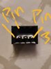
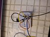
im using a rs pro k7805m-1000r3 dc to dc converter. as per the circuit for the item with capacitors (see picture attached) i suffered the capacitor on the voltage out blow up when the volts got to 10.2volts on the input side. what have i done wrong? ive attached how i did the pcb wire up.

cheers Michael
 

Attachments

  • 1.jpg
    1.jpg
    145.3 KB · Views: 242
  • 2.jpg
    2.jpg
    182.5 KB · Views: 242
  • 3.jpg
    3.jpg
    1.5 MB · Views: 251
What type of capacitors are they? If they are polarised, is the polarity correct?

Other than that, it could just be the wire lengths that are upsetting things; even a normal 7805 type regulator can oscillate with more than a couple of inches between the device and the capacitors.

Looking again, I believe you have the regulator reversed? This is one of those RS switching regs in one of our products; the pins are offset towards the green connector and the input is at the left or near end in the two photos respectively - what you show as Pin 3 in the photo:

IMG_4371.jpg IMG_4372.jpg
 
I agree with rjenkinsgb that you seem to have pins 1 and 3 swapped.

What LED light are you using? LEDs alone need a current-limited supply, so will blow when connected directly to 5 V. LED lamps have current limiter in them, but anything made for automotive use will be designed for 12 V already.
 
cheers guys, turned out it was the capacitor that was the wrong way. yeah ive got a resistor inline for the led. the problem is the led lamps that ive built for my car havent got any protection as the orignal plan was to have the controlled through a arduino.
i just want a circuit that will protect the led as the input voltage will be anywhere from 11.8 to 14.6 depending on if the engine is running or not.

That small a change isn't going to make any real difference, apply ohms law and see what the current difference will be. It will however, make the brightness vary somewhat, if that's an issue - but I don't recall LED lights on cars using any regulators?.
 
That small a change isn't going to make any real difference, apply ohms law and see what the current difference will be. It will however, make the brightness vary somewhat, if that's an issue - but I don't recall LED lights on cars using any regulators?.
A lot of vehicle LED lights use constant current regulators.

Car manufacturers usually rate devices on cars to a wider range than 11.8 to 14.6 V. They are often rated 9 - 16 V.

I tested an LED rear light assembly getting on for 10 years ago. The current was constant from 9 - 16 V. Outside that range, the lights turned off.

More powerful LED vehicle lights often use switching regulators. The ones Wipac offer are actually rated 9 - 33 V.

https://www.wipac-led.com/find-out-more
 
Some headlight modules like the Olson Flat Black from Osram have 5 LEDs in series for a 15v Vf and a boost converter is used to bump the voltage up to 17V+, then a constant current regulator is used to maintain 1.5A. Obviously a huge heat sink is required for each module.
 
LED headlights definitely have constant current regulator circuits.

Sorry, I was thinking other than headlights which are rather a specialised case (and I love mine), I've replaced lot's of LED's in rear lights on cars and there's only ever been current limiting resistors in them.
 
Sorry, I was thinking other than headlights which are rather a specialised case (and I love mine), I've replaced lot's of LED's in rear lights on cars and there's only ever been current limiting resistors in them.
LED replacement lamps for the 6 and 21 W bulbs are on the simpler end of the range.

LED light clusters, whether for cars or trailers, tend to be more sophisticated.
 
LED replacement lamps for the 6 and 21 W bulbs are on the simpler end of the range.

LED light clusters, whether for cars or trailers, tend to be more sophisticated.

I've never repaired bulbs, only clusters - interestingly the first time I did one, I obtained the exact right SM LED's from RS Components, which came in a large spool (FAR more than the handful I wanted), however, as it was for a Mercedes price wasn't an issue, and they weren't expensive any way. Every one I did after that used the exact same LED's, so the spool came in handy.

As I understand it?, more modern designs often use CAN bus or such, rather than simple 12V feeds as for a bulb.

Thinking on?, presumably all the ones I've changed have been for brake lights? - and presumably the LED's were red? - it was were I used to work, so I haven't seen them for a while now.
As far as I know, CANbus to the light cluster is rare. It is usually simple 12 V feeds from a module, or LIN. I have seen CANbus to headlights, where the functions are far more complicated.

"CANbus" when referring to car lights often refers to bulb failure detection, rather than any direct connection to a CANbus. It is called "CANbus compatible" because too many people associate that sort of bulb failure detection with cars with CANbus, when they are two separate technologies that arrived on cars within about 10 years of each other.

A lot of LED lights called "CANbus compatible" have resistors in parallel which reduces the voltage across them when just a few mA comes from the bulb failure detection circuit. Without that, an LED light will often need more than 6 V or so before it starts to take current. The resistor will prevent the some bulb failure detection circuits from triggering whenever the lamp is off.

Some cars measure the current when the light it turned on, so those resistors in parallel don't help, and just lead to increased heat and premature failure.
 
Status
Not open for further replies.

Latest threads

New Articles From Microcontroller Tips

Back
Top