Electro Tech is an online community (with over 170,000 members) who enjoy talking about and building electronic circuits, projects and gadgets. To participate you need to register. Registration is free. Click here to register now.
Welcome to our site! Electro Tech is an online community (with over 170,000 members) who enjoy talking about and building electronic circuits, projects and gadgets. To participate you need to register. Registration is free. Click here to register now.
Thanks Audioguru for your quick reply to fevers question.
Correct! it won't work.
Just in words now.
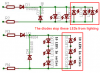
[Phase] - [18 kOhm 1 Watt R] - [LED LED LED LED LED ....... LED biassed one way in parrallel with LED LED LED ....LED reversed way] - [18 kOhm 1 Watt] - [Neutral].
I haven't got a drawing programme so i will take a photo and add it later.
thanks for the circuit diagram.
but the 4148 and 4007 diodes are missing.4007 is in series with the phase side resistor but what abt the 4148.how shld i connect it.
and is the resistor the only thing which decides the life of the whole circuit?
bcz till now i used ur circuit for only 1 LED(since 1year with continuous usage of at least 10Hrs)
20 LED circuit will draw pretty amount of current.so is this circuit suitable for 10-12Hrs operation?
Calculate how low is the LED current. The peak current is only 7mA and 8mA. The average current is less than 3mA. LEDs are rated for continuous operation at 20mA and their max allowed continuous current is 30mA.
I would feel a lot more confortable if the leds were connected
antiparallel, it's the only way to be make sure that the reverse
voltage is evenly divided amongst all leds.
Or is it just me being paranoid ?
In between posts here on this forum we had a 10 MVA, 33 kV / 11 kV substation blow up in my area and lost power for 3 hours.
I was called out to do power restoration HV switching and fault assesment of the transformer. cause, overload and old cable
on1aag
You can do it the way you suggested as well, each pair of LED's in antiparrallel and make up a series string with 10 of those LED pairs.
It is interesting how a DC LED lamp topic turns out into an AC LED lamp topic. Still good to keep all bits together.
I have halloween fogger with a skull with led eyes.
I am in the process of putting a fader on the eyes, but that is another thread.
Can someone explain the original circuit. Each eye is in series with an 82K resistor and connected to the 120 volt line. The eyes are in parallel. I could find no diodes nor capicators in the circuit.
This site uses cookies to help personalise content, tailor your experience and to keep you logged in if you register.
By continuing to use this site, you are consenting to our use of cookies.