Continue to Site

Welcome to our site!

Electro Tech is an online community (with over 170,000 members) who enjoy talking about and building electronic circuits, projects and gadgets. To participate you need to register. Registration is free. Click here to register now.

  • Welcome to our site! Electro Tech is an online community (with over 170,000 members) who enjoy talking about and building electronic circuits, projects and gadgets. To participate you need to register. Registration is free. Click here to register now.

110V dc electric motor with 4 wires

Status
Not open for further replies.

jurilica

New Member
I have 110V dc electric motor with gearbox that I need to connect to power supply.
How to connet to power supply + and - with 4 wires
2 wires are black and have red dots and other 2 wires are black

Thanks for any help
 

Attachments

  • IMG_181214124.JPG
    IMG_181214124.JPG
    55.7 KB · Views: 236
  • IMG_1813414141414.JPG
    IMG_1813414141414.JPG
    82.8 KB · Views: 177
  • img_18151144051515.jpg
    img_18151144051515.jpg
    64.7 KB · Views: 202
This looks like a shunt wound motor.
I am not sure about that Les, have a look at the rating plate where it clearly states "SERIES".

It would be helpful if Jurilica could measure the resistance between the connectors.

If this is a shunt wound motor, the field winding resistance will be much higher than if it is series wound.

JimB
 
Hi Jim,
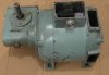
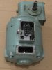
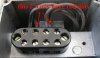
You are right. I foolishly looked at the low speed on the label and made the assumption that it was a shunt motor. I had missed the fact that it was a geared motor. Two of the wires will go to the brushes and two will go to the field coils. The field coils will probably have a lower resistance than the armature.With your multimeter identify the wires. Connect the wires that go to the brushes in series with the wires that go to the field coil and connect the two free ends to your 110 volt DC supply. (The polarity does not matter.) If you want to reverse the motor reverse the connections to either the field coils or the brushes. (But not both.) Thanks again Jim, The information I posted would have burned the motor out.

Les.
 
Last edited:
I remove some plates from motor and took pictures, maybe this help.

To alter rotation change over these leads on brush holders

Does it mater color of wires, from left to right
black - black with red dot - black - black with red dot
 

Attachments

  • IMG_181814414.JPG
    IMG_181814414.JPG
    48.5 KB · Views: 160
  • IMG_1822424.JPG
    IMG_1822424.JPG
    38.9 KB · Views: 154
  • IMG_18191414.JPG
    IMG_18191414.JPG
    41.1 KB · Views: 154
Last edited:
You need to identify the two pairs of wires that show continuity between them with your multimeter or identify then by tracing where they go to inside the motor. I have no idea of the significance of the red dots.

Les.
 
Can this help
I think than confirms that this is a series motor.

The field winding has a resistance of about 5 Ohm, if that were connected across 110v DC there would be a current of 20 amps or so flowing, and a smell of burning wires!

So to make the motor run correctly, connect terminal 2 to terminal 3, and connect the 110v supply to terminals 1 and 4.

Do you agree Les?

JimB
 
Hi Jim,
Yes I agree. It's a good job that you spotted my error before jurilica. connected it up the way I suggested in post #2.

Les.
 
The plate states Series.
That appears to be an Extremely low RPM (195 rpm) for a Series motor unless it has a reduction of some kind.
As normal for a series field, It will operate in a run-away condition so a load should always be attached.
Max.
 
Last edited:
As normal for a series field, It will operate in a run-away condition so a load should always be attached.
Correct.
Just like most car starter motors, with no load they will run very fast.

JimB
 
Hi Max,
You jumped to the wrong false conclusion that I did. The OP does state that the motor has a gearbox which I missed. I also missed series written on the label. When he came back with the resistance reading I would have realised my error.

Les.
 
Pictures of electric motor with gearbox
 

Attachments

  • IMG_18241414.JPG
    IMG_18241414.JPG
    43.1 KB · Views: 155
  • IMG_18251414.JPG
    IMG_18251414.JPG
    49.7 KB · Views: 149
How do you intend powering it? In theory it should also run on AC.
But if there is a 110/120vac supply where you are you would just need a bridge rectifier, a 10a or 20a would be more than sufficient.
Max.
 
Yes it should run on that, often these motors have simple variable Triac control off of AC.
With a bridge for the motor if DC.
Max.
 
Hi Max,
If the core of the field coils was made of a solid piece of metal rather than laminations the motor would probably not work well on AC due to eddy currents in the core. If the core is laminated I can't see why it should not work on AC.

Les.
 
Status
Not open for further replies.

Latest threads

New Articles From Microcontroller Tips

Back
Top