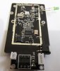
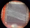
I do not think these ICs are having issue. Normally low power ICs would not be easily damaged. do a voltage measurement from ground to corner pins, normally one of the corner pin will be connected to +V (VDD). if you measure voltage then there could be oscillator issue. If the VDD pin is not receiving voltage then you can check the voltage regulator that looks like a transistor on the board.