This document presents several 555 timer circuits and there usage for a robotic obstacle avoidance system.
There are no 555 circuits presented here that are novel nor original, what makes this design unique is in its usage of basic 555 timer building blocks. The Timerbot is designed that it will continually move forward until an obstacle is in its path at which time the Timerbot will switch the right wheel off and the left wheel will run in reverse for a predetermined time and again detect an obstacle or not.
Several iterations are expected. The Timerbot serves as a demonstration of emitters, sensors and the versatility of the NE 555 timer IC.
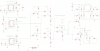
Schematic
Please see attached files.
Theory of Operation
There are 5 functional blocks and each block will be explained in this document.

Figure 1. Functional Block Diagram
Collision Transponder
IC1 is a NE555 timer and is configured in astable mode and continuously pulses LED 1 at around a 40KHz rate. LED 1 is an IR LED. The IR LED will emit IR light and reflect upon an obstacle when in close proximity.
Collision Detect/One Shot
IC2 also a NE 555 timer, in conjunction with Q10 comprises the collision detector and one shot. When an obstacle is close enough, LED 1 emissions will be detected by IR phototransistor Q10. This will trigger IC2 to output a high going pulse for roughly 250 msec. This pulse is used to control the duty cycle of the motor drive circuit explained below.
PWM H-Bridge Controller
IC3, 555 timer comprises the main motor control of the Timerbot. In normal operation, IC3 runs as an astable oscillator at about 25 KHz around 80% duty Cycle which drives both left and right motors in a forward direction. During collision detect, IC2 will output a high going pulse, which will be exclusive OR’ed (which consist of Q1-4 and Q6-9) with main motor drive signal thus inverting the 80% duty cycle to a 20% cycle and drives left motor reverse and right motor off.
Although the XOR function of Q1-4 and Q6-9 is a rather outdated approach as a simple XOR gate could be used in its place, it does help on learn the basic principles of logic design.
Left Motor Controller
The left motor controller is a full H-bridge motor driver using locked anti-phase drive. During normal operation IC3 outputs a 50% duty cycle, Q8, Q9 and Q2 are enabled turning the motor in the forward direction. Upon collision detect, the drive signal is about 20% and the motor reverses its direction.
Right Motor Controller
The right motor controller is set in a half H-bridge configuration. This was done to allow both drivers to operate in a similar manner during forward drive. Upon collision detection, the right motor drive will simply turn off while left motor reverse occurs. This results in the Timerbot backing into a southern easterly direction, relatively speaking.
Parts List
EAGLE Version 5.8.0 Copyright (c) 1988-2010 CadSoft
Part Value Device Package Library Sheet
C1 .01uf C2,5-3 C2.5-3 capacitor-wima 1
C2 .01uf C2,5-3 C2.5-3 capacitor-wima 1
C4 C2,5-3 C2.5-3 capacitor-wima 1
C5 .01uf C2,5-3 C2.5-3 capacitor-wima 1
C6 1uf C2,5-3 C2.5-3 capacitor-wima 1
C7 .01uf C2,5-3 C2.5-3 capacitor-wima 1
C8 .01uf C2,5-3 C2.5-3 capacitor-wima 1
C9 .01uf C2,5-3 C2.5-3 capacitor-wima 1
C10 .1uf C2,5-3 C2.5-3 capacitor-wima 1
D7 1N4004 1N4004 DO41-10 diode 1
D8 1N4004 1N4004 DO41-10 diode 1
D9 1N4004 1N4004 DO41-10 diode 1
D10 1N4004 1N4004 DO41-10 diode 1
D11 1N4004 1N4004 DO41-10 diode 1
D12 1N4004 1N4004 DO41-10 diode 1
G1 AB9V AB9V AB9V battery 1
IC1 NE555N NE555N DIL08 linear 1
IC2 NE555N NE555N DIL08 linear 1
IC3 NE555N NE555N DIL08 linear 1
LED1 LED5MM LED5MM SparkFun 1
Q1 2N3904 2N3904 TO92 transistor 1
Q2 2N3904 2N3904 TO92 transistor 1
Q3 2N3904 2N3904 TO92 transistor 1
Q4 2N3904 2N3904 TO92 transistor 1
Q5 2N3904 2N3904 TO92 transistor 1
Q6 2N3904 2N3904 TO92 transistor 1
Q7 2N3904 2N3904 TO92 transistor 1
Q8 2N3904 2N3904 TO92 transistor 1
Q9 2N3904 2N3904 TO92 transistor 1
Q10 LPT80A LPT80A LPT80A opto-trans-siemens 1
Q11 2N3906 2N3906 TO92 transistor-pnp 1
Q12 2N3904 2N3904 TO92 transistor 1
Q13 2N3906 2N3906 TO92 transistor-pnp 1
Q14 2N3904 2N3904 TO92 transistor 1
Q15 2N3904 2N3904 TO92 transistor 1
Q16 2N3906 2N3906 TO92 transistor-pnp 1
Q17 2N3904 2N3904 TO92 transistor 1
R1 22 R-US_V234/12 V234/12 resistor 1
R2 470 R-US_V234/12 V234/12 resistor 1
R3 470 R-US_V234/12 V234/12 resistor 1
R4 22 R-US_V234/12 V234/12 resistor 1
R5 1.2k R-US_V234/12 V234/12 resistor 1
R6 1.2k R-US_V234/12 V234/12 resistor 1
R7 120 R-US_V234/12 V234/12 resistor 1
R8 10k R-US_V234/12 V234/12 resistor 1
R9 247k R-US_V234/12 V234/12 resistor 1
R10 2k R-US_V234/12 V234/12 resistor 1
R11 2k R-US_V234/12 V234/12 resistor 1
R12 1k R-US_V234/12 V234/12 resistor 1
R13 1k R-US_V234/12 V234/12 resistor 1
R14 1k R-US_V234/12 V234/12 resistor 1
R15 470 R-US_V234/12 V234/12 resistor 1
R16 470 R-US_V234/12 V234/12 resistor 1
R17 22 R-US_V234/12 V234/12 resistor 1
R18 470 R-US_V234/12 V234/12 resistor 1
R19 470 R-US_V234/12 V234/12 resistor 1
R20 1k R-US_V234/12 V234/12 resistor 1
R21 1k R-US_V234/12 V234/12 resistor 1
R22 1k R-US_V234/12 V234/12 resistor 1
R23 1k R-US_V234/12 V234/12 resistor 1
R24 1k R-US_V234/12 V234/12 resistor 1
R25 1k R-US_V234/12 V234/12 resistor 1
R26 1k R-US_V234/12 V234/12 resistor 1
R27 1k R-US_V234/12 V234/12 resistor 1
R28 470 R-US_V234/12 V234/12 resistor 1
R29 1k R-US_V234/12 V234/12 resistor 1
R30 470 R-US_V234/12 V234/12 resistor 1
X3 22-23-2021 22-23-2021 22-23-2021 con-molex 1
X4 22-23-2021 22-23-2021 22-23-2021 con-molex 1
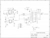
Timerbot Revamped
Now that the 555 contest is over, I wanted to revamp my timerbot entry without the constraints imposed on the in the contest which only allowed the use of 555 IC's . This design uses 1 556 IC 1 Nand gate IC and 1 Dual Hbridge IC. This should still function like the original contest entry. I have been working on a PCB for it as well but ran into a few snags getting a few nets to route. I was hoping someone might step up to help with my PCB layout. In the meantime here is the schematic.

There are no 555 circuits presented here that are novel nor original, what makes this design unique is in its usage of basic 555 timer building blocks. The Timerbot is designed that it will continually move forward until an obstacle is in its path at which time the Timerbot will switch the right wheel off and the left wheel will run in reverse for a predetermined time and again detect an obstacle or not.
Several iterations are expected. The Timerbot serves as a demonstration of emitters, sensors and the versatility of the NE 555 timer IC.
Schematic
Please see attached files.
Theory of Operation
There are 5 functional blocks and each block will be explained in this document.
Figure 1. Functional Block Diagram
Collision Transponder
IC1 is a NE555 timer and is configured in astable mode and continuously pulses LED 1 at around a 40KHz rate. LED 1 is an IR LED. The IR LED will emit IR light and reflect upon an obstacle when in close proximity.
Collision Detect/One Shot
IC2 also a NE 555 timer, in conjunction with Q10 comprises the collision detector and one shot. When an obstacle is close enough, LED 1 emissions will be detected by IR phototransistor Q10. This will trigger IC2 to output a high going pulse for roughly 250 msec. This pulse is used to control the duty cycle of the motor drive circuit explained below.
PWM H-Bridge Controller
IC3, 555 timer comprises the main motor control of the Timerbot. In normal operation, IC3 runs as an astable oscillator at about 25 KHz around 80% duty Cycle which drives both left and right motors in a forward direction. During collision detect, IC2 will output a high going pulse, which will be exclusive OR’ed (which consist of Q1-4 and Q6-9) with main motor drive signal thus inverting the 80% duty cycle to a 20% cycle and drives left motor reverse and right motor off.
Although the XOR function of Q1-4 and Q6-9 is a rather outdated approach as a simple XOR gate could be used in its place, it does help on learn the basic principles of logic design.
Left Motor Controller
The left motor controller is a full H-bridge motor driver using locked anti-phase drive. During normal operation IC3 outputs a 50% duty cycle, Q8, Q9 and Q2 are enabled turning the motor in the forward direction. Upon collision detect, the drive signal is about 20% and the motor reverses its direction.
Right Motor Controller
The right motor controller is set in a half H-bridge configuration. This was done to allow both drivers to operate in a similar manner during forward drive. Upon collision detection, the right motor drive will simply turn off while left motor reverse occurs. This results in the Timerbot backing into a southern easterly direction, relatively speaking.
Parts List
EAGLE Version 5.8.0 Copyright (c) 1988-2010 CadSoft
Part Value Device Package Library Sheet
C1 .01uf C2,5-3 C2.5-3 capacitor-wima 1
C2 .01uf C2,5-3 C2.5-3 capacitor-wima 1
C4 C2,5-3 C2.5-3 capacitor-wima 1
C5 .01uf C2,5-3 C2.5-3 capacitor-wima 1
C6 1uf C2,5-3 C2.5-3 capacitor-wima 1
C7 .01uf C2,5-3 C2.5-3 capacitor-wima 1
C8 .01uf C2,5-3 C2.5-3 capacitor-wima 1
C9 .01uf C2,5-3 C2.5-3 capacitor-wima 1
C10 .1uf C2,5-3 C2.5-3 capacitor-wima 1
D7 1N4004 1N4004 DO41-10 diode 1
D8 1N4004 1N4004 DO41-10 diode 1
D9 1N4004 1N4004 DO41-10 diode 1
D10 1N4004 1N4004 DO41-10 diode 1
D11 1N4004 1N4004 DO41-10 diode 1
D12 1N4004 1N4004 DO41-10 diode 1
G1 AB9V AB9V AB9V battery 1
IC1 NE555N NE555N DIL08 linear 1
IC2 NE555N NE555N DIL08 linear 1
IC3 NE555N NE555N DIL08 linear 1
LED1 LED5MM LED5MM SparkFun 1
Q1 2N3904 2N3904 TO92 transistor 1
Q2 2N3904 2N3904 TO92 transistor 1
Q3 2N3904 2N3904 TO92 transistor 1
Q4 2N3904 2N3904 TO92 transistor 1
Q5 2N3904 2N3904 TO92 transistor 1
Q6 2N3904 2N3904 TO92 transistor 1
Q7 2N3904 2N3904 TO92 transistor 1
Q8 2N3904 2N3904 TO92 transistor 1
Q9 2N3904 2N3904 TO92 transistor 1
Q10 LPT80A LPT80A LPT80A opto-trans-siemens 1
Q11 2N3906 2N3906 TO92 transistor-pnp 1
Q12 2N3904 2N3904 TO92 transistor 1
Q13 2N3906 2N3906 TO92 transistor-pnp 1
Q14 2N3904 2N3904 TO92 transistor 1
Q15 2N3904 2N3904 TO92 transistor 1
Q16 2N3906 2N3906 TO92 transistor-pnp 1
Q17 2N3904 2N3904 TO92 transistor 1
R1 22 R-US_V234/12 V234/12 resistor 1
R2 470 R-US_V234/12 V234/12 resistor 1
R3 470 R-US_V234/12 V234/12 resistor 1
R4 22 R-US_V234/12 V234/12 resistor 1
R5 1.2k R-US_V234/12 V234/12 resistor 1
R6 1.2k R-US_V234/12 V234/12 resistor 1
R7 120 R-US_V234/12 V234/12 resistor 1
R8 10k R-US_V234/12 V234/12 resistor 1
R9 247k R-US_V234/12 V234/12 resistor 1
R10 2k R-US_V234/12 V234/12 resistor 1
R11 2k R-US_V234/12 V234/12 resistor 1
R12 1k R-US_V234/12 V234/12 resistor 1
R13 1k R-US_V234/12 V234/12 resistor 1
R14 1k R-US_V234/12 V234/12 resistor 1
R15 470 R-US_V234/12 V234/12 resistor 1
R16 470 R-US_V234/12 V234/12 resistor 1
R17 22 R-US_V234/12 V234/12 resistor 1
R18 470 R-US_V234/12 V234/12 resistor 1
R19 470 R-US_V234/12 V234/12 resistor 1
R20 1k R-US_V234/12 V234/12 resistor 1
R21 1k R-US_V234/12 V234/12 resistor 1
R22 1k R-US_V234/12 V234/12 resistor 1
R23 1k R-US_V234/12 V234/12 resistor 1
R24 1k R-US_V234/12 V234/12 resistor 1
R25 1k R-US_V234/12 V234/12 resistor 1
R26 1k R-US_V234/12 V234/12 resistor 1
R27 1k R-US_V234/12 V234/12 resistor 1
R28 470 R-US_V234/12 V234/12 resistor 1
R29 1k R-US_V234/12 V234/12 resistor 1
R30 470 R-US_V234/12 V234/12 resistor 1
X3 22-23-2021 22-23-2021 22-23-2021 con-molex 1
X4 22-23-2021 22-23-2021 22-23-2021 con-molex 1
Timerbot Revamped
Now that the 555 contest is over, I wanted to revamp my timerbot entry without the constraints imposed on the in the contest which only allowed the use of 555 IC's . This design uses 1 556 IC 1 Nand gate IC and 1 Dual Hbridge IC. This should still function like the original contest entry. I have been working on a PCB for it as well but ran into a few snags getting a few nets to route. I was hoping someone might step up to help with my PCB layout. In the meantime here is the schematic.