Presented here is a significant step forward in simple, cheep, and efficient boost converter designs for the electronic hobbyists arsenal. The circuits main selling point is that it has the remarkable ability to create stable and clean 5-9 volts energy from an input voltage more than 0.7 volts. The operation from very low voltage is significant. When a 1.6 volt alkaline cell goes dead the voltage will drop off very flat and evenly. Most devices, like digital cameras will stop operating at around 1.4 volts per cell. Using 0.2 volts of the cells total energy is quite wasteful, there is so much more energy still available that most electronic devices make you throw out. It can be done better...
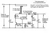
The Scavenger solves the above dilemma by (more or less) adding the cells input voltage to it's self, then using that to charge a capacitor. The circuit repeats this process several times until the output voltage reaches a "programmed" set point. Then the circuit goes into a dormant state where it consumes little energy. The output will simply coast off the charged capacitor (as if it was the battery) until the voltage on it has dropped enough for the circuit to start back up again. The advantage this process creates is that the output voltage is no longer dependent on the condition of the battery. As long as there is enough POWER at the input to run the whole system, it will self correct the voltage to a large degree. The disadvantage to such a system is that the conversion process wastes some power. So to make an effective design, we must convert the current to voltage as efficiently as possible. And this circuit is very good at this as well. Here is the preliminary schematic...

Notes:
Q1 is the main power switching device. You can use any normal NPN transistor that you may find. For best results though, it is recommended you use a high-end switching transistor. This will boost both power AND efficiency with no draw backs. These transistors are harder to find in salvage. You will almost certainly have to buy them. But they are not very expensive, even if they are uncommon-ish.
T1 is a simple 1:1 ratio transformer of not too critical design. It is usually made by hand out of a small ferrite core wrapped with two strands or magnet wire at 10-30 turns. The wires are then switched around and two are attached to each other. Another way is to use a 1:1 center taped transformer. The main point is that one coil go one way around the core, and the other should go the other. This is indicated by the two dots on the schematic. One should definitely NOT use laminated steel cores as the eddy losses will be very high.
Zd1 is the "program" for the voltage output. It is a simple zener diode. These can be pulled from other power supply's, or bought brand new. It is important to know that they look just like normal diodes, but they are totally different. They actually *DO* conduct in the reverse direction, which is backwards thinking. They are an odd part, most will not just have them lying around. It *IS* possible to use normal diodes, or even LED's in place of this part. But it is up to you to compute the resulting voltage from the combination of substitute parts you use. And the diode or LED needs to point the other way from what is shown in the schematic.
D1 *COULD* be replaced with just any diode you find lying around. But for best efficiency it really should be a Schottky diode. Schottky diodes are so common that there really is no reason not to use one. And they cost about the same.
Pros of this circuit.
Will start and run from 3.2 volts, down to 0.7 volts, with up to 5 Ohms cell ESR.
Uses every last drop of a cells energy, even past 0.7 volts. Reducing waste.
Can supply 500-1000mW of usable power under optimal conditions.
Has greater than 90% efficiency under most conditions. 95+% with careful tuning.
Uses the most common of parts. And not very many of them.
Is fairly small and light. The inductor is the largest part.
Has good regulation, and acceptable ripple for most things.
All operational parameters can be 100% adjusted for almost any need or condition.
Simple enough to be built by the novice with high likelihood of success.
Virtually no possibility for electrocution.
Should be more ESD and EMP safe than typical IC based DC-DC converters.
Has natural reverse battery protection.
Cons of this circuit.
Doesn't like to start with high load and low input power.
Can become inefficient when running under sub optimal conditions.
Doesn't have any safeties. No over current, over temperature, or under voltage.
Need to run at low frequency's means bigger inductor, and more likely to make noise.
Needs a some what odd transformer/inductor. Where winding phase is important.
Transformer inductance is important, and not easy for the average person to measure.
Can really only use BJTs, where MOSFETs could yield better performance and power.
Can't have great efficiency, power, low ripple, and great regulation all at the same time.
Possibly for overvolt on Vout if the regulator section fails. Multiple points of failure.
Miniaturization is limited by the transformer. 15x15x10mm seems like the practical limit.
Can't be made to work well with voltages very close to or higher than target Vout.
New design, not 100% tested or proven. Inaccuracy's could pop up without warning.
If you need more information than the above, the thread that this project was discuses in can be found by clicking *HERE*
Many thanks to Mr RB for giving much input and ideas to try with this circuit.
The Scavenger solves the above dilemma by (more or less) adding the cells input voltage to it's self, then using that to charge a capacitor. The circuit repeats this process several times until the output voltage reaches a "programmed" set point. Then the circuit goes into a dormant state where it consumes little energy. The output will simply coast off the charged capacitor (as if it was the battery) until the voltage on it has dropped enough for the circuit to start back up again. The advantage this process creates is that the output voltage is no longer dependent on the condition of the battery. As long as there is enough POWER at the input to run the whole system, it will self correct the voltage to a large degree. The disadvantage to such a system is that the conversion process wastes some power. So to make an effective design, we must convert the current to voltage as efficiently as possible. And this circuit is very good at this as well. Here is the preliminary schematic...
Notes:
Q1 is the main power switching device. You can use any normal NPN transistor that you may find. For best results though, it is recommended you use a high-end switching transistor. This will boost both power AND efficiency with no draw backs. These transistors are harder to find in salvage. You will almost certainly have to buy them. But they are not very expensive, even if they are uncommon-ish.
T1 is a simple 1:1 ratio transformer of not too critical design. It is usually made by hand out of a small ferrite core wrapped with two strands or magnet wire at 10-30 turns. The wires are then switched around and two are attached to each other. Another way is to use a 1:1 center taped transformer. The main point is that one coil go one way around the core, and the other should go the other. This is indicated by the two dots on the schematic. One should definitely NOT use laminated steel cores as the eddy losses will be very high.
Zd1 is the "program" for the voltage output. It is a simple zener diode. These can be pulled from other power supply's, or bought brand new. It is important to know that they look just like normal diodes, but they are totally different. They actually *DO* conduct in the reverse direction, which is backwards thinking. They are an odd part, most will not just have them lying around. It *IS* possible to use normal diodes, or even LED's in place of this part. But it is up to you to compute the resulting voltage from the combination of substitute parts you use. And the diode or LED needs to point the other way from what is shown in the schematic.
D1 *COULD* be replaced with just any diode you find lying around. But for best efficiency it really should be a Schottky diode. Schottky diodes are so common that there really is no reason not to use one. And they cost about the same.
Pros of this circuit.
Will start and run from 3.2 volts, down to 0.7 volts, with up to 5 Ohms cell ESR.
Uses every last drop of a cells energy, even past 0.7 volts. Reducing waste.
Can supply 500-1000mW of usable power under optimal conditions.
Has greater than 90% efficiency under most conditions. 95+% with careful tuning.
Uses the most common of parts. And not very many of them.
Is fairly small and light. The inductor is the largest part.
Has good regulation, and acceptable ripple for most things.
All operational parameters can be 100% adjusted for almost any need or condition.
Simple enough to be built by the novice with high likelihood of success.
Virtually no possibility for electrocution.
Should be more ESD and EMP safe than typical IC based DC-DC converters.
Has natural reverse battery protection.
Cons of this circuit.
Doesn't like to start with high load and low input power.
Can become inefficient when running under sub optimal conditions.
Doesn't have any safeties. No over current, over temperature, or under voltage.
Need to run at low frequency's means bigger inductor, and more likely to make noise.
Needs a some what odd transformer/inductor. Where winding phase is important.
Transformer inductance is important, and not easy for the average person to measure.
Can really only use BJTs, where MOSFETs could yield better performance and power.
Can't have great efficiency, power, low ripple, and great regulation all at the same time.
Possibly for overvolt on Vout if the regulator section fails. Multiple points of failure.
Miniaturization is limited by the transformer. 15x15x10mm seems like the practical limit.
Can't be made to work well with voltages very close to or higher than target Vout.
New design, not 100% tested or proven. Inaccuracy's could pop up without warning.
If you need more information than the above, the thread that this project was discuses in can be found by clicking *HERE*
Many thanks to Mr RB for giving much input and ideas to try with this circuit.