This attempt at an instructional thread is in response to several experiences I've had trying to convey relay circuits to people on web forums. Not everybody is familiar with Relay Ladder Logic, as I've learned. That's a shame really, because Ladder diagrams are the most intuitive way to express relay circuits. They are much easier to read & understand than wiring diagrams. Please look at the following examples so you know what I mean:
Fish tank flusher ladder diagram Vs. Fish tank flusher wiring diagram
Automated press ladder diagram Vs. Automated press wiring diagram
Disclaimer: I'm probably not qualified to teach the following course") ...
...
But seriously, I am not an engineer and I have never had any formal training in this area. All of what I know is what I've figured out by myself (a machine maintenance technician, and a rather green one at that), so some of it is bound to be wrong. Please kindly help me fix any errors you may find. Keep in mind, this is not meant to be all-inclusive; it is just scraping the tip of the iceberg, intended to give noobs a place to start.
Ladder diagrams are found mostly in industrial machine prints with relay control schemes. They have been in heavy use I think since probably shortly after the relay was invented, and they continue to be prevalent in industry today, as this is how PLCs are programmed. You can use regular wiring diagrams to marginally convey circuits with only a couple of relays, but once you get half a dozen or more (sometimes MANY more) relays and discrete controls in a circuit, it really is not feasible to express the circuit in any other form than ladder.
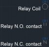
Let's get started; Here's the 3 symbols you'll be dealing with the most:
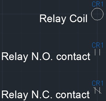
You'll find at least 2 of these in every ladder diagram you ever see, or else it's not a ladder diagram.
Before we go any further, let me just explain a relay (just in case) - A relay is an electromechanical switch. It has a set of contacts, like your typical household light switch, PLUS a solenoid-type mechanism that operates the switch. So your house lights are switched by your hand, and a relay is switched by sending current through it's coil. There are a zillion types of relays, but this tutorial focuses mainly on the general purpose type, which have one coil, and at least one set of contacts (common, normally open, normally closed).
Here's a few more symbols that you're likely to see:
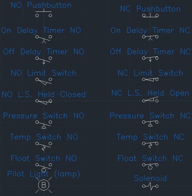
You'll notice that almost everything is marked NO or NC.
NO = Normally Open. Open means that no current can flow through.
NC = Normally closed. Closed means that current CAN flow through.
NO and NC always apply when there is nothing acting on them. What I mean to say is...uhh... How about an example: You have probably noticed that when you open the door of your car, the dome light comes on. This is because of the little push switch in the door frame. You might say that this switch is normally open, because the light is not normally on; but you would be wrong. This is a normally closed switch, which is normally held open (by the closed door). We call this a limit switch, NC, held open, and there is a special symbol for that.
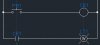
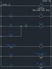
So let's dive into a small example:
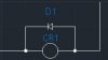
[IMGhttp://www.electro-tech-online.com/content/attachments/70695d1360304028-3.jpg.html[/IMG]
So, this could be a DC circuit or an AC circuit, it doen't really matter. The vertical line on the left represents incoming power (EX. +12VDC or 120VAC [L]) and the right side vertical line represents outgoing power (EX. 0VDC or 120VAC [N]). Let's follow this through; incoming power encounters an open pushbutton and an open relay contact. Nothing happens. You push the button (PB1) and current is permitted to flow through the pushbutton and through the relay coil. Once current flows through the relay coil, the NO contact closes, and current flows through the white pilot light. So in this circuit, you push the button, and the light comes on. You release the button, the light turns off.
You see how we named the relay CR1? This is the conventional relay naming scheme. CR stands for Control Relay. The name does not matter, so long as it is consistent. If we added another relay it would be called CR2, and the next CR3, and so on. Same for pushbuttons; PB1, PB2, so on. Limit switches; LS1, LS2, LS3, so on.
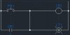
Let's take this example one step further:
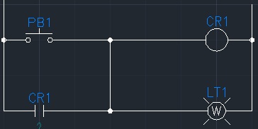
So, what I've done here is run a wire from the bottom rung to the top rung. Where I phsyically connected the wire is not important. I could have connected the wire at the relay contact and the pushbutton, or I could have connected it at the relay coil and the light; either way, the effect on the circuit is the same. So, what effect did adding this wire have? Well, it changed our circuit into a latching circuit. How it works now, is that you push the button, the relay energizes, and lights the light just as before, but now the relay contact is not only feeding the pilot light, it is also feeding back to the relay's own coil. So, when you release the button, the relay will remain energized and the light will stay on. The only way to deenergize the relay is to remove power from the circuit.
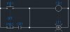
So, let's add a function to be able to turn the light off:
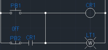
You'll see I've added a second pushbutton, PB2 - Normally closed pushbutton. I've labeled the 2 pushbuttons "ON" & "OFF" respectively. Picking up where we left off with the last example, you push PB1, the relay latches its coil ON through its own contact. The only difference now is, that the relay latches its coil ON through its own contact, AND through NC PB2. When you push PB2, the connection between incoming power and CR1 coil is broken, so it deenergizes.
Now that you've had some examples forced down your throat, let's introduce a new concept:
In ladder diagrams, a relay's NO contact and NC contact do not necessarily have to be drawn together. in fact, most often they are not. Another illustration:
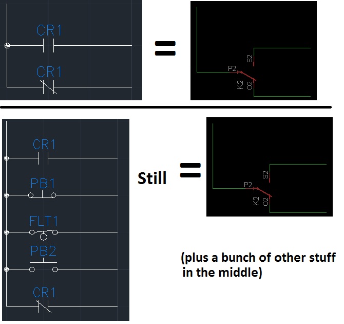
You see how ladder form gives us the freedom to place components where they make the most sense? Ladder diagrams are supposed to be drawn more or less in the order in which the sequence occurs. This way you can start at the top, and read through the diagram down to the bottom and get a quick idea how the circuit operates without poring over a spaghetti-bowl of wires like in a wiring diagram.
Some relays have multiple contacts. There are DPDT (2 sets of NO, NC, COM contacts) 4PDT (4 sets of NO, NC, COM contacts) etc. and these contacts can also be placed throughout the drawing wherever it is logical to place them.
Now, for a lesson in proper form:
In Ladder diagrams, RELAY COILS ALWAYS GO ON THE RIGHT, CONNECTED TO 0V OR NEUTRAL. Putting switches between a coil and ground violates convention, and is not a good idea to do it in real life because as the EM field in the relay coil collapses, it will arc across contacts.
Placing the relay coil with one side terminated to outgoing power, and with a flyback diode in parallel (shown below), will give the relay a good place to dump this stored energy. DO NOT use a flyback diode in an AC cricuit. (Flyback diodes may not always be indicated on the diagram):
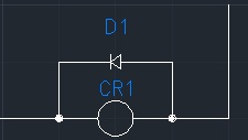
Now, this part of the convention does place limits on us that can be broken in real life. For example, it's totally possible to make an H-bridge out of relays, but if you tried to express the H-bridge in ladder form, it would break convention. You can't always have your cake and eat it too.
Timer relays:
There are several types of time delay relays. The 2 most common types are ON delay timers and OFF delay timers. An ON delay timer will not energize when power is applied to the coil; it will wait a prescribed amount of time (this can be adjustable or fixed, depending on the relay) and then it will energize. It will remain energized as long as power is applied to it. When you remove power, it will deenergize immediately. An OFF delay timer will energize instantly when power is applied to its coil, however when you remove power, it will stay energized for a prescribed amount of time (this can be adjustable or fixed, depending on the relay) and then it will deenergize.
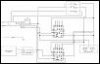
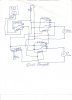
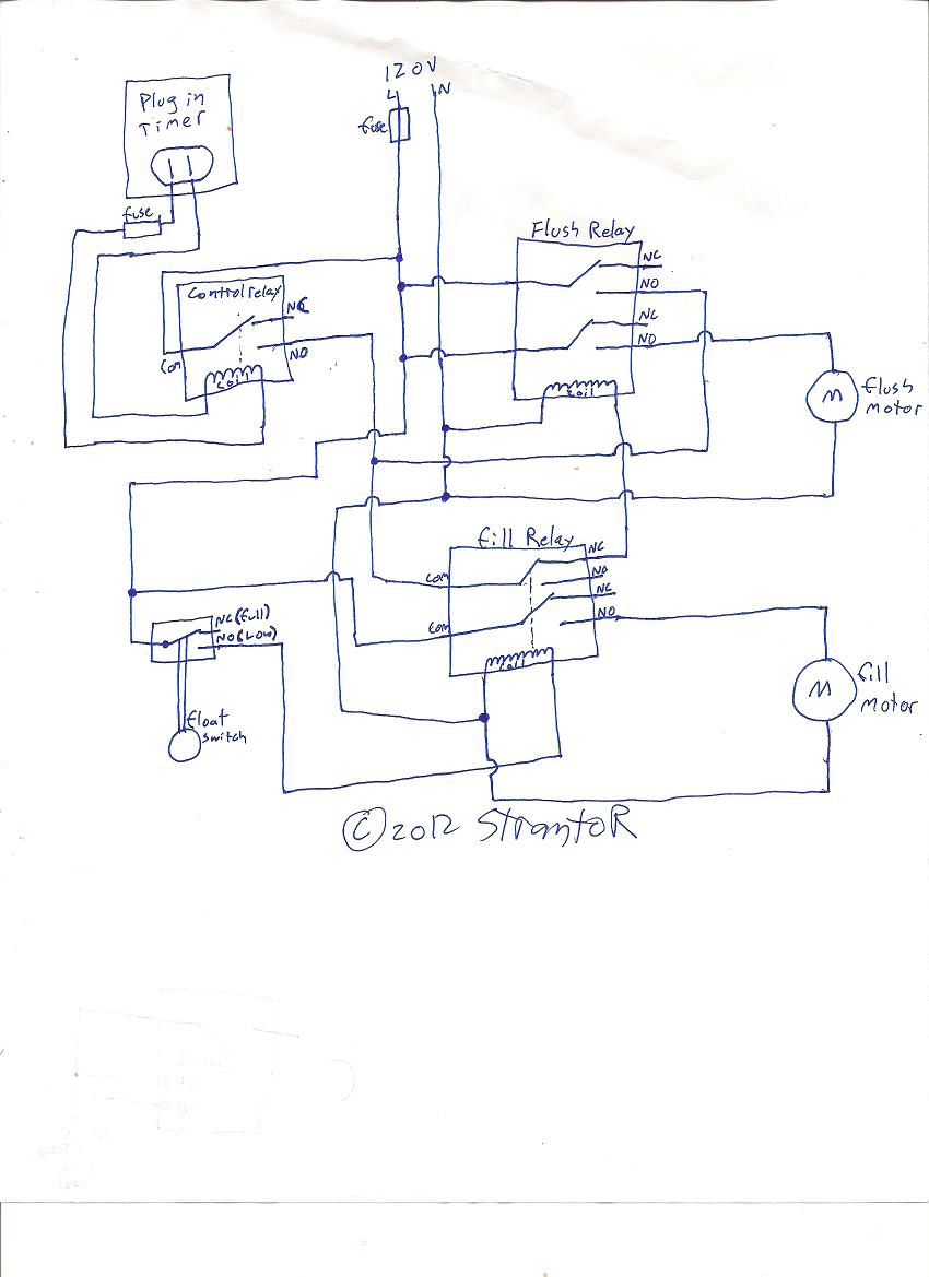
The next diagram will provide some general familiarization with ladder logic and with Timer relays:
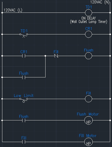
I made this diagram for a member who wanted an automatic system to replace the water in his fish tank. He had a programmable lamp timer, 2 pumps, and a float switch. I will explain it:
. Starting out, the lamp timer (TD1) is plugged in, waiting for the preset time.
. Preset time elapses, TD1 energizes for only a few seconds and then deenergizes.
. During the few seconds that TD1 is energized, CR1 is energized, which energizes the "Flush" relay.
. The flush relay latches it'self through it's own contact, and stays energized even after TD1 deenergizes and subsequently CR1 deenergizes.
. (skip down to the second rung from the bottom) The "Flush" relay is energized, which energizes the "flush" pump motor. The motor is now pumping water out of the fish tank.
. (go one rung up) The flush pump continues to run until the low limit float switch is tripped, at which time the "Fill" relay energizes.
. When the fill relay energizes, (3rd rung from the top) it breaks the Flush relay's latching circuit, and the flush pump starts.
. (bottom rung) While the fill relay is energized, the fill pump motor is running, pumping water back into the tank.
. This type of float switch will not change positions until the tank is full - it is a "snap action" adjustable float switch. Once the tank is full, the fill motor stops.
. The circuit now lies in waiting for the next time that the lamp timer elapses. If at any point between now and then, the water level goes low enough, the float switch will trigger and fill the tank again (safety measure)
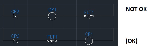
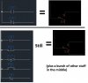
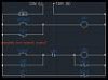
One more thing - You CAN assemble a circuit from a ladder diagram. You DO NOT NEED A WIRING DIAGRAM. The sure fire way to make sure you get it right the first time is to employ wire numbers. Wire numbers apply to points that are electrically common. Wires on either side of a switch, or either side of a relay are not electrically common. I will demonstrate:
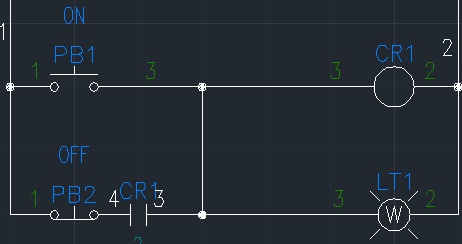
This circuit is CORRECT. There are potentially a dozen wires physically in the circuit but there are only 4 wire numbers,
1,2,4, & 4 - because several of the individual segments of wire are electrically common.
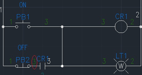
This circuit is INcorrect. Wire # 3 has been used on both sides of CR1.
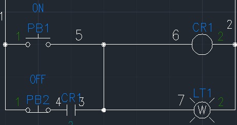
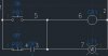
This circuit is INcorrect. Wires 5,6, & 7 are all electrically common and should carry the same wire number.
Also you have to make sure when you wire a circuit per a ladder diagram, that you terminate the incoming power to the COMMON of the relay. For example, if you want to use a relay's NO contacts to switch a pump, it is possible to route incoming power to the NO contact, route the COMMON of the relay to the pump, and route the other side of the pump to ground. HOWEVER, you will run into problems if you later want to use that same relay's NC contact for another purpose. The proper way to do it is to route incoming power to the COMMON contact, route the NO of the relay to the pump, and route the other side of the pump to ground.
Well, that’s about as far as I take this and still have it fall under the title of "Ladder Logic for NOOBS". If I have energy at a later date I will go into more complex things. As it stands I think I have relieved myself of ever having to translate a ladder diagram into a wiring diagram; from now on, if people don't get it, I will direct them here.
Fish tank flusher ladder diagram Vs. Fish tank flusher wiring diagram
Automated press ladder diagram Vs. Automated press wiring diagram
Disclaimer: I'm probably not qualified to teach the following course
...But seriously, I am not an engineer and I have never had any formal training in this area. All of what I know is what I've figured out by myself (a machine maintenance technician, and a rather green one at that), so some of it is bound to be wrong. Please kindly help me fix any errors you may find. Keep in mind, this is not meant to be all-inclusive; it is just scraping the tip of the iceberg, intended to give noobs a place to start.
Ladder diagrams are found mostly in industrial machine prints with relay control schemes. They have been in heavy use I think since probably shortly after the relay was invented, and they continue to be prevalent in industry today, as this is how PLCs are programmed. You can use regular wiring diagrams to marginally convey circuits with only a couple of relays, but once you get half a dozen or more (sometimes MANY more) relays and discrete controls in a circuit, it really is not feasible to express the circuit in any other form than ladder.
Let's get started; Here's the 3 symbols you'll be dealing with the most:
You'll find at least 2 of these in every ladder diagram you ever see, or else it's not a ladder diagram.
Before we go any further, let me just explain a relay (just in case) - A relay is an electromechanical switch. It has a set of contacts, like your typical household light switch, PLUS a solenoid-type mechanism that operates the switch. So your house lights are switched by your hand, and a relay is switched by sending current through it's coil. There are a zillion types of relays, but this tutorial focuses mainly on the general purpose type, which have one coil, and at least one set of contacts (common, normally open, normally closed).
Here's a few more symbols that you're likely to see:
You'll notice that almost everything is marked NO or NC.
NO = Normally Open. Open means that no current can flow through.
NC = Normally closed. Closed means that current CAN flow through.
NO and NC always apply when there is nothing acting on them. What I mean to say is...uhh... How about an example: You have probably noticed that when you open the door of your car, the dome light comes on. This is because of the little push switch in the door frame. You might say that this switch is normally open, because the light is not normally on; but you would be wrong. This is a normally closed switch, which is normally held open (by the closed door). We call this a limit switch, NC, held open, and there is a special symbol for that.
So let's dive into a small example:
[IMGhttp://www.electro-tech-online.com/content/attachments/70695d1360304028-3.jpg.html[/IMG]
So, this could be a DC circuit or an AC circuit, it doen't really matter. The vertical line on the left represents incoming power (EX. +12VDC or 120VAC [L]) and the right side vertical line represents outgoing power (EX. 0VDC or 120VAC [N]). Let's follow this through; incoming power encounters an open pushbutton and an open relay contact. Nothing happens. You push the button (PB1) and current is permitted to flow through the pushbutton and through the relay coil. Once current flows through the relay coil, the NO contact closes, and current flows through the white pilot light. So in this circuit, you push the button, and the light comes on. You release the button, the light turns off.
You see how we named the relay CR1? This is the conventional relay naming scheme. CR stands for Control Relay. The name does not matter, so long as it is consistent. If we added another relay it would be called CR2, and the next CR3, and so on. Same for pushbuttons; PB1, PB2, so on. Limit switches; LS1, LS2, LS3, so on.
Let's take this example one step further:
So, what I've done here is run a wire from the bottom rung to the top rung. Where I phsyically connected the wire is not important. I could have connected the wire at the relay contact and the pushbutton, or I could have connected it at the relay coil and the light; either way, the effect on the circuit is the same. So, what effect did adding this wire have? Well, it changed our circuit into a latching circuit. How it works now, is that you push the button, the relay energizes, and lights the light just as before, but now the relay contact is not only feeding the pilot light, it is also feeding back to the relay's own coil. So, when you release the button, the relay will remain energized and the light will stay on. The only way to deenergize the relay is to remove power from the circuit.
So, let's add a function to be able to turn the light off:
You'll see I've added a second pushbutton, PB2 - Normally closed pushbutton. I've labeled the 2 pushbuttons "ON" & "OFF" respectively. Picking up where we left off with the last example, you push PB1, the relay latches its coil ON through its own contact. The only difference now is, that the relay latches its coil ON through its own contact, AND through NC PB2. When you push PB2, the connection between incoming power and CR1 coil is broken, so it deenergizes.
Now that you've had some examples forced down your throat, let's introduce a new concept:
In ladder diagrams, a relay's NO contact and NC contact do not necessarily have to be drawn together. in fact, most often they are not. Another illustration:
You see how ladder form gives us the freedom to place components where they make the most sense? Ladder diagrams are supposed to be drawn more or less in the order in which the sequence occurs. This way you can start at the top, and read through the diagram down to the bottom and get a quick idea how the circuit operates without poring over a spaghetti-bowl of wires like in a wiring diagram.
Some relays have multiple contacts. There are DPDT (2 sets of NO, NC, COM contacts) 4PDT (4 sets of NO, NC, COM contacts) etc. and these contacts can also be placed throughout the drawing wherever it is logical to place them.
Now, for a lesson in proper form:
In Ladder diagrams, RELAY COILS ALWAYS GO ON THE RIGHT, CONNECTED TO 0V OR NEUTRAL. Putting switches between a coil and ground violates convention, and is not a good idea to do it in real life because as the EM field in the relay coil collapses, it will arc across contacts.
Placing the relay coil with one side terminated to outgoing power, and with a flyback diode in parallel (shown below), will give the relay a good place to dump this stored energy. DO NOT use a flyback diode in an AC cricuit. (Flyback diodes may not always be indicated on the diagram):
Now, this part of the convention does place limits on us that can be broken in real life. For example, it's totally possible to make an H-bridge out of relays, but if you tried to express the H-bridge in ladder form, it would break convention. You can't always have your cake and eat it too.
Timer relays:
There are several types of time delay relays. The 2 most common types are ON delay timers and OFF delay timers. An ON delay timer will not energize when power is applied to the coil; it will wait a prescribed amount of time (this can be adjustable or fixed, depending on the relay) and then it will energize. It will remain energized as long as power is applied to it. When you remove power, it will deenergize immediately. An OFF delay timer will energize instantly when power is applied to its coil, however when you remove power, it will stay energized for a prescribed amount of time (this can be adjustable or fixed, depending on the relay) and then it will deenergize.
The next diagram will provide some general familiarization with ladder logic and with Timer relays:
I made this diagram for a member who wanted an automatic system to replace the water in his fish tank. He had a programmable lamp timer, 2 pumps, and a float switch. I will explain it:
. Starting out, the lamp timer (TD1) is plugged in, waiting for the preset time.
. Preset time elapses, TD1 energizes for only a few seconds and then deenergizes.
. During the few seconds that TD1 is energized, CR1 is energized, which energizes the "Flush" relay.
. The flush relay latches it'self through it's own contact, and stays energized even after TD1 deenergizes and subsequently CR1 deenergizes.
. (skip down to the second rung from the bottom) The "Flush" relay is energized, which energizes the "flush" pump motor. The motor is now pumping water out of the fish tank.
. (go one rung up) The flush pump continues to run until the low limit float switch is tripped, at which time the "Fill" relay energizes.
. When the fill relay energizes, (3rd rung from the top) it breaks the Flush relay's latching circuit, and the flush pump starts.
. (bottom rung) While the fill relay is energized, the fill pump motor is running, pumping water back into the tank.
. This type of float switch will not change positions until the tank is full - it is a "snap action" adjustable float switch. Once the tank is full, the fill motor stops.
. The circuit now lies in waiting for the next time that the lamp timer elapses. If at any point between now and then, the water level goes low enough, the float switch will trigger and fill the tank again (safety measure)
One more thing - You CAN assemble a circuit from a ladder diagram. You DO NOT NEED A WIRING DIAGRAM. The sure fire way to make sure you get it right the first time is to employ wire numbers. Wire numbers apply to points that are electrically common. Wires on either side of a switch, or either side of a relay are not electrically common. I will demonstrate:
This circuit is CORRECT. There are potentially a dozen wires physically in the circuit but there are only 4 wire numbers,
1,2,4, & 4 - because several of the individual segments of wire are electrically common.
This circuit is INcorrect. Wire # 3 has been used on both sides of CR1.
This circuit is INcorrect. Wires 5,6, & 7 are all electrically common and should carry the same wire number.
Also you have to make sure when you wire a circuit per a ladder diagram, that you terminate the incoming power to the COMMON of the relay. For example, if you want to use a relay's NO contacts to switch a pump, it is possible to route incoming power to the NO contact, route the COMMON of the relay to the pump, and route the other side of the pump to ground. HOWEVER, you will run into problems if you later want to use that same relay's NC contact for another purpose. The proper way to do it is to route incoming power to the COMMON contact, route the NO of the relay to the pump, and route the other side of the pump to ground.
Well, that’s about as far as I take this and still have it fall under the title of "Ladder Logic for NOOBS". If I have energy at a later date I will go into more complex things. As it stands I think I have relieved myself of ever having to translate a ladder diagram into a wiring diagram; from now on, if people don't get it, I will direct them here.
-
 1.jpg
1.jpg -
 2.jpg
2.jpg -
 3.jpg
3.jpg -
 4.jpg
4.jpg -
 5.jpg
5.jpg -
 6.jpg
6.jpg -
 7.jpg
7.jpg -
 8.jpg
8.jpg -
 9.jpg
9.jpg -
 10.jpg
 -
 11.jpg
 -
 12.jpg
 -
 13.jpg
 -
 14.jpg
 -
 flushfill.JPG
