To save power and reduce temperature rise, a solenoid or relay coil can be initially energized with full power to rapidly complete the solenoid stroke, and then reduce its voltage (current) to just what's required to maintain the solenoid position.
Often the voltage can be lowered to 35-50% of the nominal value, reducing the power dissipated to 12-25% of nominal, a very significant reduction.
A resistor in series can be used to reduce the current, but that can dissipate significant power and require a high wattage power resistor for larger solenoids.
The most efficient method to lower the current of a DC solenoid is with a PWM (Pulse Width Modulated) signal with duty-cycle selected to give the desired hold current.
Such a circuit can dissipate less than a watt while maintaining a reduced solenoid current.
This technique can also be used to apply an initial overvoltage to the solenoid for more rapid operation, and then drop the voltage/current to a safe holding level.
This circuit uses a 555 timer with four transistors and a few passive parts to perform this function.
It energizes the solenoid coil with the full supply voltage, and after sufficient time to completely energize the solenoid (usually a few tens of ms), reduces the current to the desired hold current.
The sequence occurs upon application of a single control signal to the circuit.
The solenoid then stays energized with the PWM hold current applied until the control signal returns to zero.
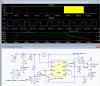
The schematic and LTspice simulation of the circuit is shown below.
When the control input voltage (In) goes high, power is applied to the 555 circuit.
This causes C3 to initially apply voltage to the gate of MOSFET M2, which turns it on. The MOSFET thus holds the timing capacitor C2 low.
This keeps the 555 OUT signal high and MOSFET M1 on, applying full voltage to the Lsolenoid coil.
When R2C3 times out, MOSFET M2 turns off. This allows the 555 to start oscillating in an astable mode with output duty-cycle determined by the setting of pot U2.
This duty-cycle sets the average voltage applied to the solenoid, i.e. a 50% pot setting/duty-cycle gives an average of 1/2 Vdd to the solenoid, reducing its current by one half.

The circuit is completely off when the control signal is low, drawing only a very small leakage current, thus using no appreciable power when the solenoid is not energized.
The time for full voltage to be initially applied to the solenoid is determined by the R2C3 time-constant.
These values can be selected to give any desired time.
The duty-cycle can be adjusted by pot U2 to give a desired hold current.
This value of this current should be selected to reliably keep the solenoid energized over any solenoid load, temperature, and supply voltage variations.
For the 6Ω simulated solenoid resistance and a 12V supply voltage, the initial current (green trace) rises to 2A after the start signal (red trace) and then drops to a ≈0.75A hold current for the indicated pot setting of 0.4 (40%) duty-cycle (yellow traces) at about ≈200ms after the start, as determined by R2C3.
At 300ms the input control pulse returns low, turning off the solenoid power and causing the solenoid current decay to zero.
The PWM frequency is determined by the value of C2 and pot U2.
The values shown give a frequency of about 1.3kHz.
This can be changed, as needed, by the value selected for C2.
If a switch is already available to control power to the solenoid, then Q1, M3, R3 and R5 can be eliminated, and the power directly applied to the circuit at V+.
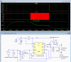
Simplified Circuit -----
If a ≥5v logic control input is desired but a small bias current from the 555 is acceptable when the solenoid is off, then the circuit below will work.
It requires only two transistors instead of four.
Note that the full power activation time of this circuit is affected by the control input peak voltage level.
The time increases with a higher control input level.

Often the voltage can be lowered to 35-50% of the nominal value, reducing the power dissipated to 12-25% of nominal, a very significant reduction.
A resistor in series can be used to reduce the current, but that can dissipate significant power and require a high wattage power resistor for larger solenoids.
The most efficient method to lower the current of a DC solenoid is with a PWM (Pulse Width Modulated) signal with duty-cycle selected to give the desired hold current.
Such a circuit can dissipate less than a watt while maintaining a reduced solenoid current.
This technique can also be used to apply an initial overvoltage to the solenoid for more rapid operation, and then drop the voltage/current to a safe holding level.
This circuit uses a 555 timer with four transistors and a few passive parts to perform this function.
It energizes the solenoid coil with the full supply voltage, and after sufficient time to completely energize the solenoid (usually a few tens of ms), reduces the current to the desired hold current.
The sequence occurs upon application of a single control signal to the circuit.
The solenoid then stays energized with the PWM hold current applied until the control signal returns to zero.
The schematic and LTspice simulation of the circuit is shown below.
When the control input voltage (In) goes high, power is applied to the 555 circuit.
This causes C3 to initially apply voltage to the gate of MOSFET M2, which turns it on. The MOSFET thus holds the timing capacitor C2 low.
This keeps the 555 OUT signal high and MOSFET M1 on, applying full voltage to the Lsolenoid coil.
When R2C3 times out, MOSFET M2 turns off. This allows the 555 to start oscillating in an astable mode with output duty-cycle determined by the setting of pot U2.
This duty-cycle sets the average voltage applied to the solenoid, i.e. a 50% pot setting/duty-cycle gives an average of 1/2 Vdd to the solenoid, reducing its current by one half.
The circuit is completely off when the control signal is low, drawing only a very small leakage current, thus using no appreciable power when the solenoid is not energized.
The time for full voltage to be initially applied to the solenoid is determined by the R2C3 time-constant.
These values can be selected to give any desired time.
The duty-cycle can be adjusted by pot U2 to give a desired hold current.
This value of this current should be selected to reliably keep the solenoid energized over any solenoid load, temperature, and supply voltage variations.
For the 6Ω simulated solenoid resistance and a 12V supply voltage, the initial current (green trace) rises to 2A after the start signal (red trace) and then drops to a ≈0.75A hold current for the indicated pot setting of 0.4 (40%) duty-cycle (yellow traces) at about ≈200ms after the start, as determined by R2C3.
At 300ms the input control pulse returns low, turning off the solenoid power and causing the solenoid current decay to zero.
The PWM frequency is determined by the value of C2 and pot U2.
The values shown give a frequency of about 1.3kHz.
This can be changed, as needed, by the value selected for C2.
If a switch is already available to control power to the solenoid, then Q1, M3, R3 and R5 can be eliminated, and the power directly applied to the circuit at V+.
Simplified Circuit -----
If a ≥5v logic control input is desired but a small bias current from the 555 is acceptable when the solenoid is off, then the circuit below will work.
It requires only two transistors instead of four.
Note that the full power activation time of this circuit is affected by the control input peak voltage level.
The time increases with a higher control input level.