I'd like to share a project that allows you to create simple LED animation sequences similar to the Knight Rider effect. This isn't a fancy feature laden project with PWM fading effects or anything like that. It's just one method, out of hundreds of different methods, that you might use to produce simple LED animation effects.
This project uses an eighteen pin PIC16F1827 microcontroller with a small assembly language program that demonstrates and exploits some of the features found in this new "enhanced mid-range" class of microntrollers from Microchip. If the "assembly language" reference hasn't scared you off, please read on.

Hardware
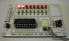
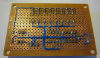
While this simple circuit could easily be cobbled together on a solderless breadboard, I chose to build it on a small Radio Shack prototype board (sku 276-149). After gluing a plastic coated paper silk-screen onto the component side of the board, I used 30 guage Kynar wire and point-to-point wiring on the copper side of the board. Please note that you must provide a regulated 5 volt d.c. supply for this project.

Parts List
Operation
The program is designed to continuously display an LED sequence contained in FX (effects) tables in the program. The program comes with several FX tables and when you power up the board it will display the sequences in the first FX table. The next sequential FX table is displayed each time you press the push button. The program will roll over to the first FX table when you press the push button while displaying the last FX table.
Editing FX Tables
The FX (effects) table data is pretty straight forward. Each table must have a label and must begin with a single <steps> byte. This is the number of sequences contained in the table and the program uses the label to automatically calculate this value. Each FX table can contain up to 255 sequences or steps and each step contains two parts; (1) the LED <pattern>, and (2) the <duration> for that pattern. The <pattern> byte is simply eight bits which match the position of the eight LEDs on the project board (bit 7 on the left to bit 0 on the right). A '1' bit will turn an LED on while a '0' bit will turn an LED off. The <duration> part of each step must contain a value from 1 to 255 which is the time the pattern will be displayed in 10-ms increments (1..255 = 10..2550 msecs). Here's what an FX table looks like (a Knight Rider type effect);
Software
The assembly language source and hex files are located in the ZIP file attachment and the program uses absolute addressing mode.
Assembly language programmers unfamiliar with features in the "enhanced mid-range" devices should note the use of FSRx/INDFx registers in the program to indirectly access 8-bit table data.
I hope this article proves helpful.
Cheerful regards, Mike

This project uses an eighteen pin PIC16F1827 microcontroller with a small assembly language program that demonstrates and exploits some of the features found in this new "enhanced mid-range" class of microntrollers from Microchip. If the "assembly language" reference hasn't scared you off, please read on.
Hardware
While this simple circuit could easily be cobbled together on a solderless breadboard, I chose to build it on a small Radio Shack prototype board (sku 276-149). After gluing a plastic coated paper silk-screen onto the component side of the board, I used 30 guage Kynar wire and point-to-point wiring on the copper side of the board. Please note that you must provide a regulated 5 volt d.c. supply for this project.
Parts List
Code:
1 ea. PIC16F1827-I/P (DIP package)
1 ea. 0.1-uf (100nf) ceramic capacitor
1 ea. 10 kOhm, 1/8th watt carbon film resistor
1 ea. generic momentary contact switch
8 ea. 3mm LED
8 ea. 470 Ohm, 1/8th watt carbon film resistor
Misc. sockets, connectors, prototype circuit board
Operation
The program is designed to continuously display an LED sequence contained in FX (effects) tables in the program. The program comes with several FX tables and when you power up the board it will display the sequences in the first FX table. The next sequential FX table is displayed each time you press the push button. The program will roll over to the first FX table when you press the push button while displaying the last FX table.
Editing FX Tables
The FX (effects) table data is pretty straight forward. Each table must have a label and must begin with a single <steps> byte. This is the number of sequences contained in the table and the program uses the label to automatically calculate this value. Each FX table can contain up to 255 sequences or steps and each step contains two parts; (1) the LED <pattern>, and (2) the <duration> for that pattern. The <pattern> byte is simply eight bits which match the position of the eight LEDs on the project board (bit 7 on the left to bit 0 on the right). A '1' bit will turn an LED on while a '0' bit will turn an LED off. The <duration> part of each step must contain a value from 1 to 255 which is the time the pattern will be displayed in 10-ms increments (1..255 = 10..2550 msecs). Here's what an FX table looks like (a Knight Rider type effect);
Code:
fx02
        dt      (fx03-fx02)/2   ; <steps>
        dt      b'00000001',8   ; <pattern>, <duration>
        dt      b'00000010',8   ;
        dt      b'00000100',8   ;
        dt      b'00001000',8   ;
        dt      b'00010000',8   ;
        dt      b'00100000',8   ;
        dt      b'01000000',8   ;
        dt      b'10000000',8   ;
        dt      b'01000000',8   ;
        dt      b'00100000',8   ;
        dt      b'00010000',8   ;
        dt      b'00001000',8   ;
        dt      b'00000100',8   ;
        dt      b'00000010',8   ;
fx03
Software
The assembly language source and hex files are located in the ZIP file attachment and the program uses absolute addressing mode.
Assembly language programmers unfamiliar with features in the "enhanced mid-range" devices should note the use of FSRx/INDFx registers in the program to indirectly access 8-bit table data.
I hope this article proves helpful.
Cheerful regards, Mike