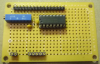
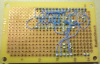
Here's a relatively simple Backpack design for HD44780 type LCD character displays that requires just two I/O pins on the host microcontroller while driving the LCD display in its "8-bit" interface mode. You should also be able to use a 74HC164 shift register instead of a 74HC595 (untested).

Theory of Operation
Note that the 'E' line from the microcontroller is directly connected to the 'RCK' pin on the 74HC595 and the 'E' pin on the LCD. In this way the 'E' line performs double duty by latching data from the 74HC595 internal shift register onto its outputs during the rising edge of the 'E' signal pulse and then writes those 8 data bits, as well as the LCD 'RS' bit, to the LCD on the falling edge of the 'E' signal pulse.
The 'CLK' line from the microcontroller is directly connected to the 'SCK' (serial clock) pin on the 74HC595 and the 'RS' (register select) pin on the LCD. The 'CLK' pin also drives an RC integrator which in turn drives the 'SER' shift register data input pin on the 74HC595. This configuration allows the 'CLK' line to produce both the data and clock signals used to load the 74HC595 shift register as well as the 'RS' signal used to write the LCD.
RC integrator component values were chosen for a a time constant (tau) of 3.3-us which is just long enough to accommodate PIC clock speeds down to a minimum of 4-MHz (Tcy = 1-us). Clocking a bit into the 74HC595 shift register involves setting the 'CLK' line to either '1' or '0' and waiting ~10-us to charge or drain the RC integrator before taking the 'CLK' line low and then high to shift the '0' or '1' level on the integrator output into the 74HC595 shift register via the 'SER' input.
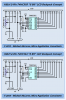
The chart below shows the 'CLK' signal (integrator input) in pink and integrator output to the 74HC595 'SER' pin in blue. The '0' or '1' value on the 'SER' pin is clocked into the 74HC595 on each 'CLK' rising edge. Note that the time required to write a byte (and 'RS' bit) to the LCD is approximately 100-us.

Example Low-Level Drivers in C (BoostC)
Example Backpack low-level drivers are provided in the program attached below. It's for a PIC18F14K22 device and it was written using the free/lite version of BoostC. The RA1 and RA2 I/O pins connect to the Backpack 'CLK' and 'E' lines, respectively.
Have fun... Cheerful regards, Mike


Theory of Operation
Note that the 'E' line from the microcontroller is directly connected to the 'RCK' pin on the 74HC595 and the 'E' pin on the LCD. In this way the 'E' line performs double duty by latching data from the 74HC595 internal shift register onto its outputs during the rising edge of the 'E' signal pulse and then writes those 8 data bits, as well as the LCD 'RS' bit, to the LCD on the falling edge of the 'E' signal pulse.
The 'CLK' line from the microcontroller is directly connected to the 'SCK' (serial clock) pin on the 74HC595 and the 'RS' (register select) pin on the LCD. The 'CLK' pin also drives an RC integrator which in turn drives the 'SER' shift register data input pin on the 74HC595. This configuration allows the 'CLK' line to produce both the data and clock signals used to load the 74HC595 shift register as well as the 'RS' signal used to write the LCD.
RC integrator component values were chosen for a a time constant (tau) of 3.3-us which is just long enough to accommodate PIC clock speeds down to a minimum of 4-MHz (Tcy = 1-us). Clocking a bit into the 74HC595 shift register involves setting the 'CLK' line to either '1' or '0' and waiting ~10-us to charge or drain the RC integrator before taking the 'CLK' line low and then high to shift the '0' or '1' level on the integrator output into the 74HC595 shift register via the 'SER' input.
The chart below shows the 'CLK' signal (integrator input) in pink and integrator output to the 74HC595 'SER' pin in blue. The '0' or '1' value on the 'SER' pin is clocked into the 74HC595 on each 'CLK' rising edge. Note that the time required to write a byte (and 'RS' bit) to the LCD is approximately 100-us.
Example Low-Level Drivers in C (BoostC)
Example Backpack low-level drivers are provided in the program attached below. It's for a PIC18F14K22 device and it was written using the free/lite version of BoostC. The RA1 and RA2 I/O pins connect to the Backpack 'CLK' and 'E' lines, respectively.
Have fun... Cheerful regards, Mike