In some low level analog signal applications a single frequency interfering noise signal, such as from a 50/60Hz main's frequency, can be a problem, and it is suppressed with a notch filter that has a high attenuation at that frequency.
A problem when using a high-Q notch filter to reject such a specific frequency, is that it generally is required to tweak the notch frequency due to component tolerances, so that the notch center is exactly at the desired frequency.
Unfortunately, most typical notch circuits require changing the value of more than one component to alter the frequency without significantly affecting the filter Q (notch depth and width).
But here's a state-variable type filter circuit by Alain Temps that generates a notch whose attenuation and notch width are largely independent of component tolerances, and the notch frequency can be adjusted with a single potentiometer to the required value, again without significantly affecting the response Q.
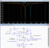
The circuit schematic is shown below.
The notch frequency is Fo= 1/(2π*Rf1C1*(Rf2+R6)C2), with the values shown giving a notch at 60Hz.
The simulation shows the notch frequency adjustment change for 0%, 50%, and 100% rotation of the trimpot, U_Rf2.
The simulated notch is below -60dB. This can vary some, depending upon the gain-bandwidth of the op amp used.
The Q of the notch can be varied by changing the value of R4. with lower values reducing the Q and increasing the width of the notch.
Generic op amps are shown, but just about any general purpose op amp should work for such low notch frequencies.
Higher notch frequency notches may require higher frequency op amps for a deep null.
A quad version op amp will require only one IC package for the circuit.
Note that if you power the op amps from a single supply, you will need to generate a virtual ground at 1/2 the supply voltage and offset the signal to that voltage (or AC couple the signal).
A particular shortcoming of this circuit is that its dynamic range is limited due to high internal peak signal voltages at the null frequency, which can be as much as 24dB above the input signal level.
This means a 1Vpk input signal can generate a 16Vpk internal signal, which means the op amp supply voltages would need to be at least ±16V with a rail-rail type op amp.
You can minimize that voltage by attenuating the input signal and increasing the gain of U4 (which is set to give an output/input gain of 1 in the simulation) to compensate at the output.
Alternately lowering the Q of the circuit by reducing the value of R4 will also reduce the internal peak voltages, at the expense of a wider notch frequency.

A problem when using a high-Q notch filter to reject such a specific frequency, is that it generally is required to tweak the notch frequency due to component tolerances, so that the notch center is exactly at the desired frequency.
Unfortunately, most typical notch circuits require changing the value of more than one component to alter the frequency without significantly affecting the filter Q (notch depth and width).
But here's a state-variable type filter circuit by Alain Temps that generates a notch whose attenuation and notch width are largely independent of component tolerances, and the notch frequency can be adjusted with a single potentiometer to the required value, again without significantly affecting the response Q.
The circuit schematic is shown below.
The notch frequency is Fo= 1/(2π*Rf1C1*(Rf2+R6)C2), with the values shown giving a notch at 60Hz.
The simulation shows the notch frequency adjustment change for 0%, 50%, and 100% rotation of the trimpot, U_Rf2.
The simulated notch is below -60dB. This can vary some, depending upon the gain-bandwidth of the op amp used.
The Q of the notch can be varied by changing the value of R4. with lower values reducing the Q and increasing the width of the notch.
Generic op amps are shown, but just about any general purpose op amp should work for such low notch frequencies.
Higher notch frequency notches may require higher frequency op amps for a deep null.
A quad version op amp will require only one IC package for the circuit.
Note that if you power the op amps from a single supply, you will need to generate a virtual ground at 1/2 the supply voltage and offset the signal to that voltage (or AC couple the signal).
A particular shortcoming of this circuit is that its dynamic range is limited due to high internal peak signal voltages at the null frequency, which can be as much as 24dB above the input signal level.
This means a 1Vpk input signal can generate a 16Vpk internal signal, which means the op amp supply voltages would need to be at least ±16V with a rail-rail type op amp.
You can minimize that voltage by attenuating the input signal and increasing the gain of U4 (which is set to give an output/input gain of 1 in the simulation) to compensate at the output.
Alternately lowering the Q of the circuit by reducing the value of R4 will also reduce the internal peak voltages, at the expense of a wider notch frequency.