Introduction--
Stepping motors usually require a high voltage pulse (high being higher than the winding voltage at the nominal operating current) to reduce the effect of the L/R time-constant and give a fast current rise in the inductive winding, which is then typically followed by a lower voltage/current hold to minimize power dissipation in the motor.
This is often done with a power resistor in series with the winding or a constant-current circuit, both of which waste significant power in the resistor or constant-current transistor.
Described here is a 555 PWM circuit that initially applies full voltage to the winding to generate a fast risetime step, followed by a PWM hold to efficiently reduce the motor voltage and current.
Thus minimum power is required and it is nearly all dissipated in the motor windings.
Description--
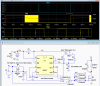
The circuit below consists of a 555 astable multi-vibrator with adjustable duty-cycle to generate the PWM signal.
The MOSFET gate signal is gated by the Schmitt-trigger NAND gates U3 and U4.
The rising edge of the motor winding phase signal (V2) initially causes U4 to fully turn on MOSFET M1 and apply full voltage to the motor winding.
After a time-delay determined by R2 and C3, U3 applies the PWM signal from the 555 through U4 to the MOSFET gate, reducing the average voltage, and thus current and power to the motor winding until the phase signal returns to zero.
(D4 provides for rapid discharge of C3, to be ready for the next phase cycle.)
The R2C3 delay is selected to be approximately equal to the mechanical step time, which maximises the step torque and allows for the maximum step frequency.
The PWM duty-cycle is adjusted to give the minimum current needed to maintain the motor at its step position.
Simulation--
The LTspice simulation below shows the signal at the MOSFET gate, V(g) stays high
for about 9ms, as determined by R2C3, before the PWM signal starts (here with a ≈13kHz frequency adjusted to about a 40% PWM duty-cycle, both of which can be changed as desired for the application).
The gate signal then returns to zero with the input, shutting off the winding current.

Application--
Three CD4049 inverter gates in parallel are used as a poor-man's gate driver to rapidly charge and discharge the large MOSFET gate charge.
The simulation shows a gate voltage rise and fall times of <1μs, giving low switching dissipation in the MOSFET.
The circuit is shown driving one MOSFET, which in many stepper motor applications would be the lower MOSFET of a bridge driving the motor winding (only one of the bottom MOSFETs in a bridge needs to receive the PWM signal at a time).
Extra logic gating may be required to route the signal to the desired MOSFET for the particular signal phase.
Note that one 555 can be used for all phases, but each phase will require its own R2. C3, D4, and gates U3 through U7. (Each gate type requires 1/2 IC package per phase).
Stepping motors usually require a high voltage pulse (high being higher than the winding voltage at the nominal operating current) to reduce the effect of the L/R time-constant and give a fast current rise in the inductive winding, which is then typically followed by a lower voltage/current hold to minimize power dissipation in the motor.
This is often done with a power resistor in series with the winding or a constant-current circuit, both of which waste significant power in the resistor or constant-current transistor.
Described here is a 555 PWM circuit that initially applies full voltage to the winding to generate a fast risetime step, followed by a PWM hold to efficiently reduce the motor voltage and current.
Thus minimum power is required and it is nearly all dissipated in the motor windings.
Description--
The circuit below consists of a 555 astable multi-vibrator with adjustable duty-cycle to generate the PWM signal.
The MOSFET gate signal is gated by the Schmitt-trigger NAND gates U3 and U4.
The rising edge of the motor winding phase signal (V2) initially causes U4 to fully turn on MOSFET M1 and apply full voltage to the motor winding.
After a time-delay determined by R2 and C3, U3 applies the PWM signal from the 555 through U4 to the MOSFET gate, reducing the average voltage, and thus current and power to the motor winding until the phase signal returns to zero.
(D4 provides for rapid discharge of C3, to be ready for the next phase cycle.)
The R2C3 delay is selected to be approximately equal to the mechanical step time, which maximises the step torque and allows for the maximum step frequency.
The PWM duty-cycle is adjusted to give the minimum current needed to maintain the motor at its step position.
Simulation--
The LTspice simulation below shows the signal at the MOSFET gate, V(g) stays high
for about 9ms, as determined by R2C3, before the PWM signal starts (here with a ≈13kHz frequency adjusted to about a 40% PWM duty-cycle, both of which can be changed as desired for the application).
The gate signal then returns to zero with the input, shutting off the winding current.
Application--
Three CD4049 inverter gates in parallel are used as a poor-man's gate driver to rapidly charge and discharge the large MOSFET gate charge.
The simulation shows a gate voltage rise and fall times of <1μs, giving low switching dissipation in the MOSFET.
The circuit is shown driving one MOSFET, which in many stepper motor applications would be the lower MOSFET of a bridge driving the motor winding (only one of the bottom MOSFETs in a bridge needs to receive the PWM signal at a time).
Extra logic gating may be required to route the signal to the desired MOSFET for the particular signal phase.
Note that one 555 can be used for all phases, but each phase will require its own R2. C3, D4, and gates U3 through U7. (Each gate type requires 1/2 IC package per phase).