For best charging of lead-acid batteries a 3-step technique is often used, consisting of an initial constant-current charge, then a high constant-voltage top-off, and finally a lower constant voltage trickle-charge.
But a simpler two-step technique can also work fairly well, which is to start with a constant-current until the battery reaches a specific voltage, indicating it is near a full charge (≈90%), and then revert to a constant-voltage mode at a lower, trickle-charge voltage to avoid over-charge while topping off and then maintaining the battery charge.
Discussion--
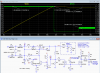
This two-step charge could be controlled with a microprocessor, of course, but below is the LTspice simulation of a relatively simple analog circuit to perform the function.
M1 and Q2 initially act as a constant-current circuit with a battery current as determined by sense resistor Rcc's value.
(A modified design with a pot adjustable charging current is discussed at the end of this article).
When the voltage reaches ≈ 14.4V indicating a near full-charge, the TL431 2.5V reference U1 detects this voltage through a voltage divider consisting of R10, R2, and R3 (M2 is biased on during the CC charge). U1 then starts to control the series P-MOSFET M1 through differential transistors Q1 and Q3, changing circuit operation to a constant voltage mode.
This mode drops Q3's collector voltage, turning off MOSFET M2 and removing resistor R3 from the circuit, which reduces the regulation set-point output voltage from 14.4V to ≈13.6V.
The battery voltage then settles to this 13.6V trickle charge value, where it will draw current as needed to top off and maintain the charge.
The circuit has a low dropout voltage of only about 0.6V, so a low input supply voltage can be used to minimize power dissipation in the series regulator transistor, M1. (This compares to a dropout voltage of more than 2V for LM317 type regulators.)
An advantage of this, is that it should allow the rectified/filtered output of a standard 12.6Vac output transformer to be used as its power supply.
Otherwise a larger, higher voltage, and more expensive transformer would be needed, such as with an LM317 type regulator, along with the larger heat sink required from the series-pass transistor increased dissipation.
LED D2 illuminates when a battery is connected and charging in the CC mode.
LED D3 illuminates when the battery is in the trickle-charge mode or no battery is connected.
If you don't need those indicators, then the LEDs plus M3 and associated parts can be eliminated.

The simulated charge voltage trip point and trickle charge voltages are typical values for a 12.6V lead acid battery.
These can be adjusted, if needed, by changing the values of R2, R3, and R10.
R10 and R2 must be calculated first to determine the CV trickle charge voltage (to give 2.5V at U1's input, Vref).
Then you select the value of R3 (which forms a circuit consisting of R10 in parallel with R2 and R3) to determine the charge voltage at which it changes from the CC mode to the CV mode (again for a voltage of 2.5V at Vref).
The selected charging current, equal to ≈0.61V / Rcc, is determined by the battery capacity.
(The maximum set charging limit is primarily determined by the current capacity of the series regulator P-MOSFET selected, and the amount of power it can dissipate with its heatsink.)
Typically, for good battery life, you want to charge no faster than the 10-hour rate for its ampere-hour capacity, i.e. a 6Ah battery should be charged at no more than 0.6A, giving an Rcc value of 1Ω.
The charging values to use are further discussed here.
For the circuit with a pot adjustable CC setting, see the end of this paper.
Simulation--
The LTspice simulation shows a constant battery charge current, I(Rbat), of ≈1.22A, as set by a Rcc value of 0.5Ω, until a V(Out) of 14.38V is reached, at which point the circuit goes into the trickle-charge mode with the output voltage dropping to ≈13.57V.
The input voltage should be ≥15V with a maximum of about 20V.
The circuit has a low drop-out of about 0.6V and the closer the supply is to 15V, the less dissipation in transistor M1.
This means a standard 12.6Vac output transformer into a full-wave bridge Schottky rectifier, as shown in the simulation, should work as a supply.
It does require sufficient filtering so that the low point on the ripple voltage is not much lower than 15V (at least 5mF of filter capacitance per amp of current).
Note that the transformer RMS current rating should be at least 40% (1.4) above the charger's DC current-limit value to avoid overheating the transformer. The DC current is taken at the peak AC output by the rectifiers, which is 1.4 times the RMS voltage, requiring 1.4 times the transformer power for a given current.
A good alternate supply is a 15V, wall wart switching power adapter. They are relatively inexpensive, small, and efficient. Just size it for the maximum battery charge current you want.
Except for low maximum charge current and input voltage, M1 will need to be on a heatsink since it will be dissipating [V(in)-V(out)] * I(out) watts with V(out) being the battery voltage during the constant-current charge.
Pot Adjustable Current Setting--
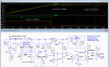
Below is the circuit with a more complex constant-current design (described here) that allows adjustment of the charging current from zero to the maximum, useful if you charge different size batteries and want to easily adjust the current for each battery's requirements.
This design also has the advantage of a lower maximum voltage drop (about 240mv versus 700mv), with better current stability. This lowers the circuit dropout voltage to < ½ volt.
The simulation results are the same as the fixed current design above except for the charging current.
The current-limit pot, U2, is stepped for wiper settings of 25% 50% and 100%, giving charging currents of 0.75A, 1.35A and 2.6A.
(The simulated battery size is also stepped proportionally to the current so the charging times are similar.)
The charge current can be adjusted from zero to a maximum of ≈ 2.6A.
This maximum can be changed by using a different value for the Rlim current sense resistor. Its value is 0.26 / Ilim(max).

But a simpler two-step technique can also work fairly well, which is to start with a constant-current until the battery reaches a specific voltage, indicating it is near a full charge (≈90%), and then revert to a constant-voltage mode at a lower, trickle-charge voltage to avoid over-charge while topping off and then maintaining the battery charge.
Discussion--
This two-step charge could be controlled with a microprocessor, of course, but below is the LTspice simulation of a relatively simple analog circuit to perform the function.
M1 and Q2 initially act as a constant-current circuit with a battery current as determined by sense resistor Rcc's value.
(A modified design with a pot adjustable charging current is discussed at the end of this article).
When the voltage reaches ≈ 14.4V indicating a near full-charge, the TL431 2.5V reference U1 detects this voltage through a voltage divider consisting of R10, R2, and R3 (M2 is biased on during the CC charge). U1 then starts to control the series P-MOSFET M1 through differential transistors Q1 and Q3, changing circuit operation to a constant voltage mode.
This mode drops Q3's collector voltage, turning off MOSFET M2 and removing resistor R3 from the circuit, which reduces the regulation set-point output voltage from 14.4V to ≈13.6V.
The battery voltage then settles to this 13.6V trickle charge value, where it will draw current as needed to top off and maintain the charge.
The circuit has a low dropout voltage of only about 0.6V, so a low input supply voltage can be used to minimize power dissipation in the series regulator transistor, M1. (This compares to a dropout voltage of more than 2V for LM317 type regulators.)
An advantage of this, is that it should allow the rectified/filtered output of a standard 12.6Vac output transformer to be used as its power supply.
Otherwise a larger, higher voltage, and more expensive transformer would be needed, such as with an LM317 type regulator, along with the larger heat sink required from the series-pass transistor increased dissipation.
LED D2 illuminates when a battery is connected and charging in the CC mode.
LED D3 illuminates when the battery is in the trickle-charge mode or no battery is connected.
If you don't need those indicators, then the LEDs plus M3 and associated parts can be eliminated.
The simulated charge voltage trip point and trickle charge voltages are typical values for a 12.6V lead acid battery.
These can be adjusted, if needed, by changing the values of R2, R3, and R10.
R10 and R2 must be calculated first to determine the CV trickle charge voltage (to give 2.5V at U1's input, Vref).
Then you select the value of R3 (which forms a circuit consisting of R10 in parallel with R2 and R3) to determine the charge voltage at which it changes from the CC mode to the CV mode (again for a voltage of 2.5V at Vref).
The selected charging current, equal to ≈0.61V / Rcc, is determined by the battery capacity.
(The maximum set charging limit is primarily determined by the current capacity of the series regulator P-MOSFET selected, and the amount of power it can dissipate with its heatsink.)
Typically, for good battery life, you want to charge no faster than the 10-hour rate for its ampere-hour capacity, i.e. a 6Ah battery should be charged at no more than 0.6A, giving an Rcc value of 1Ω.
The charging values to use are further discussed here.
For the circuit with a pot adjustable CC setting, see the end of this paper.
Simulation--
The LTspice simulation shows a constant battery charge current, I(Rbat), of ≈1.22A, as set by a Rcc value of 0.5Ω, until a V(Out) of 14.38V is reached, at which point the circuit goes into the trickle-charge mode with the output voltage dropping to ≈13.57V.
The input voltage should be ≥15V with a maximum of about 20V.
The circuit has a low drop-out of about 0.6V and the closer the supply is to 15V, the less dissipation in transistor M1.
This means a standard 12.6Vac output transformer into a full-wave bridge Schottky rectifier, as shown in the simulation, should work as a supply.
It does require sufficient filtering so that the low point on the ripple voltage is not much lower than 15V (at least 5mF of filter capacitance per amp of current).
Note that the transformer RMS current rating should be at least 40% (1.4) above the charger's DC current-limit value to avoid overheating the transformer. The DC current is taken at the peak AC output by the rectifiers, which is 1.4 times the RMS voltage, requiring 1.4 times the transformer power for a given current.
A good alternate supply is a 15V, wall wart switching power adapter. They are relatively inexpensive, small, and efficient. Just size it for the maximum battery charge current you want.
Except for low maximum charge current and input voltage, M1 will need to be on a heatsink since it will be dissipating [V(in)-V(out)] * I(out) watts with V(out) being the battery voltage during the constant-current charge.
Pot Adjustable Current Setting--
Below is the circuit with a more complex constant-current design (described here) that allows adjustment of the charging current from zero to the maximum, useful if you charge different size batteries and want to easily adjust the current for each battery's requirements.
This design also has the advantage of a lower maximum voltage drop (about 240mv versus 700mv), with better current stability. This lowers the circuit dropout voltage to < ½ volt.
The simulation results are the same as the fixed current design above except for the charging current.
The current-limit pot, U2, is stepped for wiper settings of 25% 50% and 100%, giving charging currents of 0.75A, 1.35A and 2.6A.
(The simulated battery size is also stepped proportionally to the current so the charging times are similar.)
The charge current can be adjusted from zero to a maximum of ≈ 2.6A.
This maximum can be changed by using a different value for the Rlim current sense resistor. Its value is 0.26 / Ilim(max).
-
 upload_2018-3-14_12-54-51.png
 -
TL431 Bat Chg 2 Stage 2.asc
-
TL431 Bat Chg 2 Stage Adj Cur.asc
-
 upload_2018-3-16_19-42-26.png
