Introduction --
Having an adjustable resistance that can carry a higher current and dissipate more power than standard potentiometers is occasionally required for testing or other purposes.
An electronic circuit is desirable for this function to avoid the high cost and limited resistance range of power rheostats. Circuits that can provide a constant adjustable current load are common, but not so much for constant adjustable resistance.
Discussed here is a circuit using an opamp and a MOSFET to simulate a variable power resistor over a 200:1 adjustment range.
Discussion --
The circuit below consists of an opamp driving a MOSFET is a circuit similar to a constant-current source with feedback across a source resistor (R1) going to ground.
The difference is that the opamp control voltage is derived from the MOSFET drain voltage. This makes the current through R1 proportional to the drain voltage, giving a linear resistance response.
The amount of feedback voltage is determined by pot U2, making the equivalent resistance adjustable.
The equivalent resistance is equal to (R1 + R1*R(U2) / R3).
For the values shown, the resistance can thus be varied from about 1Ω to 200Ω, giving a 200:1 adjustment range.
The value of R1 can be selected to give other minimum values.
The value of R3 can also be reduced to increase the adjustment range, however beyond a 200:1 adjustment range or so the adjustment starts to become non-linear,
but can be done if that's acceptable in the application.
R1 and R3 are shown connected to ground but they can be floated to a higher voltage as long as the op amp supply voltage is sufficient to keep the MOSFET in its active region.
The circuit can only operate with unipolar (positive) voltages, so cannot be used as an AC resistance.
The circuit could be modified to work for negative voltages using a P-MOSFET (and negative supply to the opamp), of course.
Simulation --
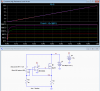
The first LTspice simulation shows the output resistance (blue trace, looking from V1 to ground) versus the pot wiper position (X-axis is pot position from 0 to 1 corresponding to 0% to 100%).
The red trace shows the current versus pot position for a 10V source voltage.

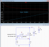
Below is the simulation for the drain voltage going from 0V to 10V for pot positions of 0%, 25%, 50% and 100%.
The resistance with voltage is quite constant above about 1-2V, depending upon the simulated resistance, so that's the practical minimum operating voltage for the circuit.

Construction --
The MOSFET dissipates power as determined by the maximum current and drain voltage in the application, so will need a heatsink to accommodate that.
R1 will dissipate power (I²R) so it's power rating should be about twice that value for the maximum current.
The opamp can be just about any rail-to-rail type.
V2 must be sufficient to power the opamp and provide the required MOSFET gate voltage for the maximum current through R1.
Having an adjustable resistance that can carry a higher current and dissipate more power than standard potentiometers is occasionally required for testing or other purposes.
An electronic circuit is desirable for this function to avoid the high cost and limited resistance range of power rheostats. Circuits that can provide a constant adjustable current load are common, but not so much for constant adjustable resistance.
Discussed here is a circuit using an opamp and a MOSFET to simulate a variable power resistor over a 200:1 adjustment range.
Discussion --
The circuit below consists of an opamp driving a MOSFET is a circuit similar to a constant-current source with feedback across a source resistor (R1) going to ground.
The difference is that the opamp control voltage is derived from the MOSFET drain voltage. This makes the current through R1 proportional to the drain voltage, giving a linear resistance response.
The amount of feedback voltage is determined by pot U2, making the equivalent resistance adjustable.
The equivalent resistance is equal to (R1 + R1*R(U2) / R3).
For the values shown, the resistance can thus be varied from about 1Ω to 200Ω, giving a 200:1 adjustment range.
The value of R1 can be selected to give other minimum values.
The value of R3 can also be reduced to increase the adjustment range, however beyond a 200:1 adjustment range or so the adjustment starts to become non-linear,
but can be done if that's acceptable in the application.
R1 and R3 are shown connected to ground but they can be floated to a higher voltage as long as the op amp supply voltage is sufficient to keep the MOSFET in its active region.
The circuit can only operate with unipolar (positive) voltages, so cannot be used as an AC resistance.
The circuit could be modified to work for negative voltages using a P-MOSFET (and negative supply to the opamp), of course.
Simulation --
The first LTspice simulation shows the output resistance (blue trace, looking from V1 to ground) versus the pot wiper position (X-axis is pot position from 0 to 1 corresponding to 0% to 100%).
The red trace shows the current versus pot position for a 10V source voltage.
Below is the simulation for the drain voltage going from 0V to 10V for pot positions of 0%, 25%, 50% and 100%.
The resistance with voltage is quite constant above about 1-2V, depending upon the simulated resistance, so that's the practical minimum operating voltage for the circuit.
Construction --
The MOSFET dissipates power as determined by the maximum current and drain voltage in the application, so will need a heatsink to accommodate that.
R1 will dissipate power (I²R) so it's power rating should be about twice that value for the maximum current.
The opamp can be just about any rail-to-rail type.
V2 must be sufficient to power the opamp and provide the required MOSFET gate voltage for the maximum current through R1.