This is an illustrated tutorial on building a voltage monitor for fan control circuits - rheostats, linear regulators like the LM317/350, and some PWM circuits. It requires a single chip, and can drive 10 LEDs with even divisions from 0V to 12V.

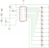
The LM3914 is a chip made specifically for driving LEDs based on voltage. A few notes about the circuit above:
The LM3914 is a chip made specifically for driving LEDs based on voltage. A few notes about the circuit above:
- Pin 9 (the Mode pin) sets whether dots or bars are used. We've tied it to +12V so it'll be on bars - tie it to ground if you want a dot.
- Notice that the LEDs are connected to +12V directly without a resistor, and current flows through them into the chip... the chip has its own current regulator built in. The size of the resistor on pin 6 (RHI) going to ground determines the current - each LED will be limited to 12.5 / R1 in amps. If R1 is 1.2Kohms, this means just barely over 10mA.
- The LM3914 is designed to "float" - this means that it'll work on any voltage up to 35V or so difference. The voltages present at RHI and RLOW set the top and low values.
- Since it's floating, to make the range easier to set, the LM3914 has a LM317 adjustable voltage regulator built in. Pin 7 (VR) is the output pin, and pin 8 (ADJ) is the adjustment pin.
- The tricky part is that if you're tying it to RHI to set the high range, you have to be careful with the resistor values in order to set the regulator properly and still keep the LEDs at the right brightness.
- To make it easier to set the LED current level, we tie ADJ to ground and tie the regulator output directly to RHI. This makes the high value 1.25volts - so, we create a voltage divider with the two resistors at far left. These convert 0-12V to 0-1.25V.
- The two capacitors keep things stable - the one at left smooths out rapid changes and spikes in the input signal, and the one at top keeps the levels from being distorted by spikes when LEDs turn on and off.

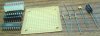
We can draw the list of parts directly from the schematic:- The LEDs - I'm using a block of 10 LEDs, since it's convenient - you can replace it with individual LEDs if you want. (Remember to change R1 to the current you want.)
- An 18-pin socket for the chip.
- The chip itself. Radioshack won't carry this chip in its stores, although it does carry it online - you'll find it cheaper online through a distributor like Jameco or Mouser. Or, try a local electronics shop.
- A small board to assemble it on.
- A 1.2KO (kiloohm) resistor, R1. I suggest 1/4 watt. This is the LED current resistor.
- A 680O (ohm) resistor, R2. 1/4 watt is fine - there will be very little current. This is the bottom half of the voltage divider.
- A 5.6KO (ohm) resistor, R3. Again, 1/4 watt is fine. This is the top half of the voltage divider.
- A 0.47 µF (microfarad, sometimes also called MFD) ceramic capacitor, C1. This keeps the input signal free of spikes. You can also use mica, monolithic, or any other kind of unpolarized capacitor.
- Finally, A 2.2 µF polarized aluminum or tantalum capacitor, C2. This insulates the power signal from the range levels, keeping spikes from the LEDs out.


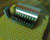
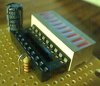
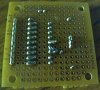
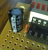
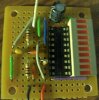
The first step is to put on the large parts, the LED and chip socket, and the electrolytic capacitor.
Keep the LED array right up against the side, as far as possible. Find out which side is the anode (the positive end) and make sure that one's on the outermost edge. Then, stick the socket in directly up next to it. The socket is one hole shorter than the 10-part LED - keep it on the bottom, so that the topmost LED (i.e. the one representing full 12V) is the one sticking out without a chip point directly next to it.
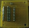
Solder all the anodes together in a line, and draw a solder line from each pin on the right to the LED cathode next to it. (The top LED is connected to pin 1 of the chip, which is the topmost on the other side - we'll stick a jumper wire in to connect it in part 5.)
Finally, stick the capacitor in directly above the chip. The negative side should point to the left, and the positive side to the right (towards the LEDs).


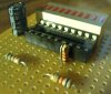
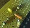
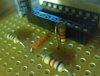
Next, put in R1, the resistor that limits LED current.
Bend one lead over, so that it goes in vertically and fits in two holes, and stick it in at pin 7 (three up from the bottom, on the left).
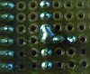
Solder it to the chip socket at the lead nearest it - see the zoom. While you're there, draw solder and connect pins 6 and 7 together. (DON'T connect the two leads of the resistor and short the resistor, or you'll not only blow the LEDs, you'll short the internal LM317 regulator.


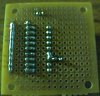
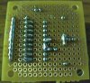
Next, we put in R2 and R3, the voltage divider resistors.
These two will be mounted parallel to the socket, on the left. Leave three holes between the chip and the two resistors, for jumper wires - also, leave a hole between them where they meet (for the jumper wire to the chip pin.) The hole where resistors meet should be straight across from pin 5.
First, solder down the two resistors, then solder the jumper wire from the point between them to pin 5.


Now, we put in C1, the anti-spike capacitor on the signal line.
This goes right in line with the jumper wire, to the left.
Solder it in so one lead of the capacitor, the two leads from the resistors, and the jumper wire are all connected - see the zoom for illustration.


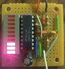
The topmost LED isn't on the right half with the rest - it's pin 1. So, we need to stick a jumper wire in.
Stick it in on top between the capacitor and socket, directly over the socket - draw some solder from pin 1 directly up to the wire, and from the wire over to the LED.


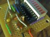
The last part is to connect all the power pins we need. This is an awfully large step, but fairly easy to do.
The wires we need to add:
- Signal in - the white wire connecting to the topmost resistor, leading out of the board
- Ground in - the black wire at the lower left
- +12V in - the red wire at the lower left
- +12V, from the top capacitor (C2) to the LEDs - green, diagonal, at the upper right
- Ground, from C2 to pin 4 of the chip - blue, vertical, up against the socket
- Ground, from C2 to pin 2 of the chip - green, vertical, to the left of the blue one above
- Ground, from C2 to the signal capacitor (C1) - gray, diagonal, at the upper left
- Ground, from ground wire to C1 - green, vertical, lower left
- Ground, from ground wire to pin 8 of the chip - orange, vertical, at the lower left by resistor R2
- +12V, from the red wire to the LEDs and C2 - purple, horizontal, lower right under the chip/LEDs
- +12V, from the red wire to pin 3 of the chip - white, bent over the pin 5 orange wire in the middle
This is the last step! Solder in all the wires and solder them as directed by the schematic - the bottom side is annotated with positions of ALL wires and parts in the board from the bottom.

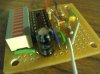
All that's left now is to hook it up! The red and black 12V/ground leads go to, obviously, 12V and ground. The question is, where do we put the signal wire?
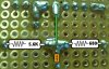
- For rheostats and voltage regulators, the signal wire connects to the + wire of the fan. If you're building this meter and the LM317 regulator on the same board, just connect the signal wire (the top of R3 in this model) to the output pin on the regulator, next to the polarized capacitor. For rheostats, you can attach it to the middle eyelet.
- For PWM circuits, it gets trickier. For my circuit (tutorial in a few days), attach it to the middle eyelet of the potentiometer controlling the duty cycle (i.e. the negative input of the op-amp. This is pin 2 on the 741, which is what most people will use.) If your PWM source doesn't give you anywhere to get a voltage-level input, you're pretty much stuck.
One last note - what if I want to use a different high value than 12V - say, 7V or 5V? In this case, get a second resistor and place it next to R1 - connect R1 to it in series, and connect this new one (call it R4) to ground. Disconnect pin 8 from ground and connect it to the middle between R1 and R4. Then, the top LED will be equal to 1.25 * (1 + R4 / R1) - it's identical to a LM317.
-
 schematic.png
 -
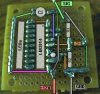
 parts.jpg
 -
 assembly-1-top.jpg
 -
 assembly-1-bottom.jpg
 -
 assembly-2-top.jpg
 -
 assembly-2-bottom.jpg
 -
 assembly-2-bottom-zoom.jpg
 -
 assembly-3-top.jpg
 -
 assembly-3-bottom.jpg
 -
 assembly-4-top.jpg
 -
 assembly-4-bottom.jpg
 -
 assembly-4-bottom-zoom.jpg
 -
 assembly-5-top.jpg
 -
 assembly-5-bottom.jpg
 -
 assembly-6-1.jpg
 -
 assembly-6-2.jpg
 -
 assembly-6-3.jpg
 -
 assembly-6-4.jpg
 -
 finished.jpg
 -
 assembly-3-top-2.jpg
