New Article (work in progress)
AMPLIFIER THEORY TUTORIAL
No matter how "digital" things get in modern consumer electronics, when it all comes down to it, after all of the digital magic is done, air must be moved for you to hear the results. An analog voltage and current must be applied to some type of device that displaces air. To displace enough air to cover the whole audio spectrum, at realistic volume levels (and some of us like it real loud....) requires quite a considerable amount of power. As Home Theater systems become bigger and more complex, they also contain more analog amplifiers (I'll cover Class D, so-called "digital" amplifiers in a separate article). My goal with this article is for the reader to gain enough knowledge to troubleshoot everything from a discrete headphone amplifier to a kilowatt PA system amp without too much difficulty. Even with the many variations in amplifier designs, they all boil down to a few basic building blocks, no matter how complex it might look on a PC board. Amplifier design and troubleshooting are not based on some "black art", but are actually quite logical and methodical. My attitude in the work I do is "An amplifier is an amplifier, and no matter how complex, they all follow some basic rules".
1. Basic Amplifier Topology
While the schematic one looks at for an amplifier might seem to be an endless sea of silicon and other components, all modern amplifiers are basically a gigantic OP-AMP. They share the same circuit elements as any op amp, and as we go along here you will begin to see the similarities. (FIG 01)
(fig01)
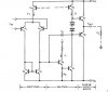
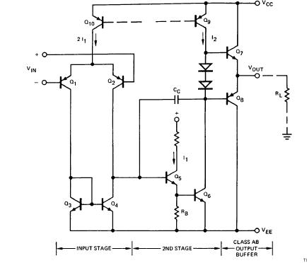
So let's look at the topology (layout) for an amplifier. In FIG02, we see three stages, an Input stage (or Diff Amp, or LTP (Long Tailed Pair)), a 2nd stage (also known as the Voltage Amplifier Stage or VAS, and a class AB output stage. Actually this diagram is that of an op amp, but as we will see an audio power amp is an oversized copy of the same device.
(fig 02)
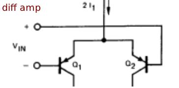
In the Input stage, we see a pair of transistors with current fed from a common current source at the emitters. There are actually two inputs here, an inverting (-) input and a noninverting (+) input, just like in an op amp. the noninverting input is usually used for the signal input, and the inverting input deals with feedback. In all audio amplifiers, the feedback exists in two distinct forms. DC feedback is applied to keep the DC offset of the amplifier output very small (generally less than +/-50mV). AC feedback sets the overall voltage gain of the amplifier, and minimizes distortion. Just as in an op amp, the inverting input tracks the noninverting input (i.e. you will see an identical copy of the waveform applied to the noninverting input appearing at the inverting input). We see a typical diff amp in fig03.
(fig 03)
Since the emitters of the transistors are fed with a single current, the outputs (in the form of collector currents) are the DIFFERENCE between the collector currents. Usually only one of the collectors is sampled to drive the next stage, but in some designs both currents are used.
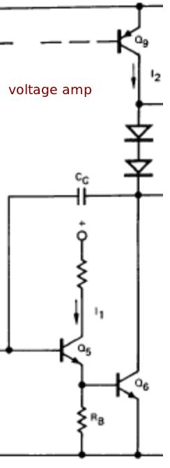
The second stage (VAS) is driven by the collector current of the noninverting input transistor. Between the diff amp and the VAS transistor, the waveform does not exist as a voltage signal, but as a current, Keep this in mind, You won't see much in the way of voltage variations if you measure this signal with an oscilloscope, and even if you do, they will seem to look very distorted. . These current variations are translated by the VAS stage back into a voltage waveform. Here, on the collector of the VAS is where signals reappear in the form of an amplified voltage. In the example of FIG04, there's actually a "composite" transistor being used, but it usually exists as a single transistor with the emitter connected to the rail, and the base going to the collector of the input transistor. You will also notice a Compensation Capacitor (Cc in FIG04). This stabilizes the amplifier and keeps it from becoming a large oscillator (more about this later). Notice also that the load for the VAS transistor is a current source. In some amplifiers, this can be a simple resistor, or a "Bootstrap" which is a pair of resistors and a capacitor used to increase the load impedance of the VAS as well as extend the voltage swing. There will be a whole section about current sources. The current source is used here as a high impedance load for the VAS, yet it can supply the required amount of current for the VAS (unlike a large value resistor).
(fig 04)
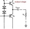
The output stage is a voltage follower buffer. As such it usually has no voltage gain, but has a high current gain.
the diodes shown set a bias voltage to keep the output transistors partially turned on. Otherwise, there would be a gap near the zero crossing of the output voltage where there is no output at all. This is called "Crossover Distortion". In an audio amplifier, the output transistors have low value (0.47 ohms or less) emitter resistors to improve thermal stability, The diodes are usually replaced with a transistor "adjustable zener" circuit, with the transistor thermally coupled to the output transistors. This bias circuit reduces the bias as the temperature rises, at the same rate that the Vbe of the output transistors decreases. This keeps the output transistors from going into thermal runaway and burning out. From the common tie point of the emitter resistors of the outputs is taken the output signal that drives the speaker. The feedback signal is also tapped off at this point.

(fig 05)
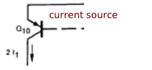
There are a couple of building blocks that need to be discussed here. Current sources and current mirrors. These are generally considered to be the parts of an amplifier that are hard to understand. Their operation is actually quite simple, and easy to troubleshoot when you know what they do. In fig06, you see a transistor with a cuirrent output, but nothing shown as to how the circuit works.
(fig 06)
In some amplifiers, there may not even be a current source feeding the diff amp or VAS, just a resistor. While this would work, these current levels will wobble or change with the signal, introducing distortion. A current source maintains a constant current, and the distortion is reduced. So how does a basic current source work?
(fig 06a)
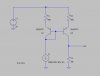
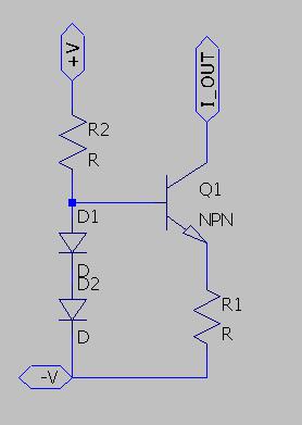
In fig06a, we have a basic constant current source. D1 and D2 set a reference voltage of 1.4V. A portion of this voltage is matched by the B-E junction of Q1, leaving 0.7V across R1. R1 sets the current by the formula of 0.7/R1=Iout. So a value of 700 ohms for R1 would give 1mA output. If for some reason, we applied a short circuit from the collector of Q1 to the positive supply, the increase in voltage across R1 would reduce the B-E voltage, reducing the current, and returning the circuit to equilibrium. The purpose of R2 is just to provide forward bias for the diodes and a small amount of base current. There are other configurations for current sources that I will add as I expand this article, but the one in fig06a is the most common in use. A few minor differences that might be found is the use of LEDs or zeners as the voltage reference. It is not uncommon to find a single voltage reference used to drive several current sources in an amplifier.
(fig 07)
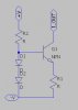
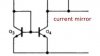
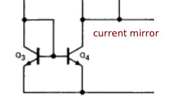
Current mirrors are basically current sources that are controlled by an input current. They are used for a number of purposes in an amplifier. A current mirror as a diff amp load can be used to force balance of the diff amp, as well as boost the gain. Current mirrors are also used to transfer drive current or the output of a current source from one part of the amp to another.
In fig 7 we see the basic current mirror as shown in the op amp schematic. The input current across the transistor diode controls the output current of the second transistor. In fig 7a, we can see how this works.
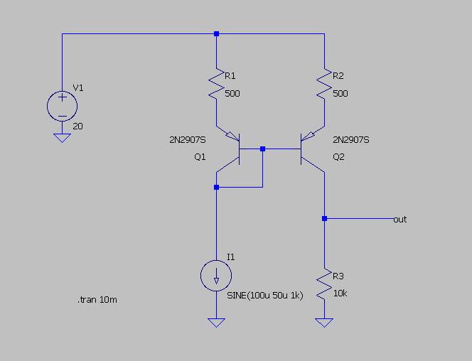
(fig 07a)
Q1 and Q2 are identical transistors. When current is drawn through the B-E junction, it sets up a voltage across R1 and Q1. The voltage across R1 is linear with current, while the voltage across the B-E junction of Q1 is not. This biases Q2 into conduction until the voltage drop across R2 is equal to the voltage across R1 (with the voltage across the two B-E junctions being equal also). The output current through Q2 and R3 is an almost identical duplicate of the input current. With this particular style of current mirror, there is a small error due to the base current of Q2 being drawn through the input side, but this error is very small. Some amp manufacturers use a simplified version of this current mirror, using a simple diode in place of Q1. There are additional errors introduced by using a diode, mainly due to the fact that the B-E junction of Q2 and the diode characteristics don't match. Again, these errors are usually very small. Current mirrors are very useful devices, and as shown in fig7a can themselves be used as a voltage amplifier stage (there is a voltage output across R3). There are devices that find use in many other parts of the electronics industry, that are made of cascaded current mirrors, and are known as Current Conveyors.
Another thing i will cover here before continuing is methods of DC offset correction. DC offset at the output of an amplifier is something to be avoided. Large offset voltages can damage speakers, and smaller offsets can cause an annoying "thump" or "pop" when an amp is connected to a speaker. There are a few methods used to control offsets. the ones i will cover here are: DC correction capacitors (the most common), DC servo amplifiers (not common, but they get used in higher end stuff), and DC offset potentiometers (not as common in amplifiers now, but they are common in older equipment).
(fig 08a)
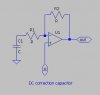
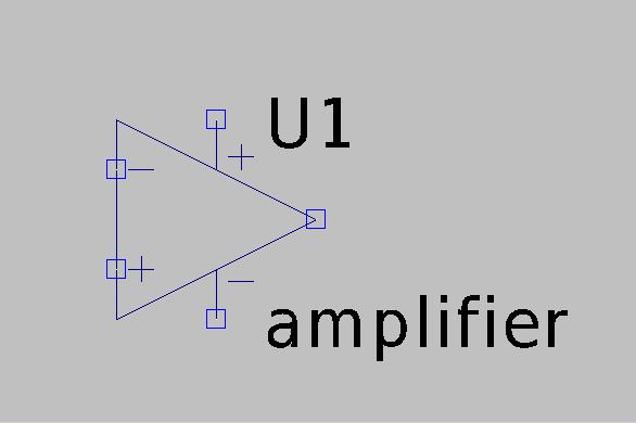
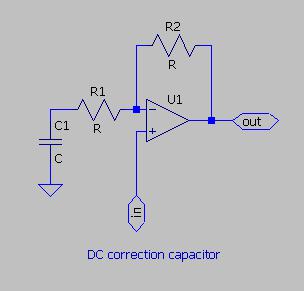
In fig 08a, U1 is the amplifier itself. R1 and R2 are the feedback resistors, and set the AC gain of the amplifier. C1 is the DC correction capacitor. Because C1 is in series with R1, the DC gain of the amplifier is 1. Any offset showing up on the output of the amplifier, shows up on the inverting input of the amplifier, forcing the output back to zero. This is the simplest method of DC correction, but has the pitfall of relying on an electrolytic capacitor. The correction cap will cause offsets if it becomes leaky, or cause loss of AC gain if it develops high ESR (from drying out). This cap would preferably be a bipolar type rated at or above the rail voltage for the amp, but many manufacturers use a polarized type, often rated much lower than the rail voltages, and sometimes bypassed with diodes to protect it from damaging voltages.
(fig 08b)
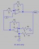
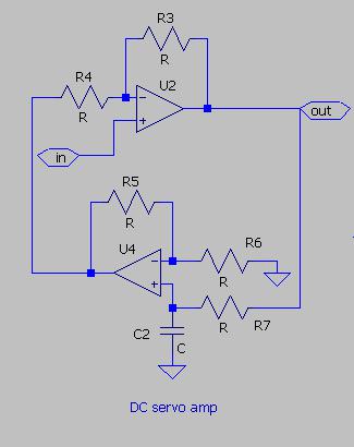
The DC servo amplifier is a very good method of DC correction, since it provides a separate feedback path for DC, and so no reactive components are in the AC feedback path to alter the audio. U2 is the amplifier itself, and U4 is an op amp used as the DC servo. U4 is a noninverting integrator, with a cutoff frequency somewhere around 5hz (the time constant is set by C2 and R7), and the integrated correction voltage is fed back in to the inverting input of the amplifier itself. Since most op amps cannot handle the rail voltages of the main amplifier, there is usually a voltage divider between the amplifier output and R7, and the servo has gain (set by R5 and R6) to compensate.
(fig 08c)
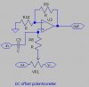
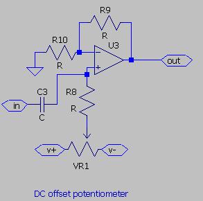
The DC offset potentiometer is a method not used very often anymore, but is seen mainly in vintage amplifiers. The simplest version of this method is shown in fig 08c, and is very similar to methods used with op amps for offset trim. The pot could also be attached to the inverting input instead of the noninverting input. The offset trimpot method was also sometimes used with either the DC correction cap or the DC servo to "preset" the offset to zero. This method does NOT actively correct for offsets due to temperature changes, part aging or other things that may cause offset problems.
This concludes the introductory section of this article. Hopefully it's enough to convey a good understanding of how amplifiers work, but as I continue this article, I will go into more detail about the inner workings of amplifier theory, as well as some of the less obvious aspects of troubleshooting.
AMPLIFIER THEORY TUTORIAL
No matter how "digital" things get in modern consumer electronics, when it all comes down to it, after all of the digital magic is done, air must be moved for you to hear the results. An analog voltage and current must be applied to some type of device that displaces air. To displace enough air to cover the whole audio spectrum, at realistic volume levels (and some of us like it real loud....) requires quite a considerable amount of power. As Home Theater systems become bigger and more complex, they also contain more analog amplifiers (I'll cover Class D, so-called "digital" amplifiers in a separate article). My goal with this article is for the reader to gain enough knowledge to troubleshoot everything from a discrete headphone amplifier to a kilowatt PA system amp without too much difficulty. Even with the many variations in amplifier designs, they all boil down to a few basic building blocks, no matter how complex it might look on a PC board. Amplifier design and troubleshooting are not based on some "black art", but are actually quite logical and methodical. My attitude in the work I do is "An amplifier is an amplifier, and no matter how complex, they all follow some basic rules".
1. Basic Amplifier Topology
While the schematic one looks at for an amplifier might seem to be an endless sea of silicon and other components, all modern amplifiers are basically a gigantic OP-AMP. They share the same circuit elements as any op amp, and as we go along here you will begin to see the similarities. (FIG 01)
(fig01)
So let's look at the topology (layout) for an amplifier. In FIG02, we see three stages, an Input stage (or Diff Amp, or LTP (Long Tailed Pair)), a 2nd stage (also known as the Voltage Amplifier Stage or VAS, and a class AB output stage. Actually this diagram is that of an op amp, but as we will see an audio power amp is an oversized copy of the same device.
(fig 02)
In the Input stage, we see a pair of transistors with current fed from a common current source at the emitters. There are actually two inputs here, an inverting (-) input and a noninverting (+) input, just like in an op amp. the noninverting input is usually used for the signal input, and the inverting input deals with feedback. In all audio amplifiers, the feedback exists in two distinct forms. DC feedback is applied to keep the DC offset of the amplifier output very small (generally less than +/-50mV). AC feedback sets the overall voltage gain of the amplifier, and minimizes distortion. Just as in an op amp, the inverting input tracks the noninverting input (i.e. you will see an identical copy of the waveform applied to the noninverting input appearing at the inverting input). We see a typical diff amp in fig03.
(fig 03)
Since the emitters of the transistors are fed with a single current, the outputs (in the form of collector currents) are the DIFFERENCE between the collector currents. Usually only one of the collectors is sampled to drive the next stage, but in some designs both currents are used.
The second stage (VAS) is driven by the collector current of the noninverting input transistor. Between the diff amp and the VAS transistor, the waveform does not exist as a voltage signal, but as a current, Keep this in mind, You won't see much in the way of voltage variations if you measure this signal with an oscilloscope, and even if you do, they will seem to look very distorted. . These current variations are translated by the VAS stage back into a voltage waveform. Here, on the collector of the VAS is where signals reappear in the form of an amplified voltage. In the example of FIG04, there's actually a "composite" transistor being used, but it usually exists as a single transistor with the emitter connected to the rail, and the base going to the collector of the input transistor. You will also notice a Compensation Capacitor (Cc in FIG04). This stabilizes the amplifier and keeps it from becoming a large oscillator (more about this later). Notice also that the load for the VAS transistor is a current source. In some amplifiers, this can be a simple resistor, or a "Bootstrap" which is a pair of resistors and a capacitor used to increase the load impedance of the VAS as well as extend the voltage swing. There will be a whole section about current sources. The current source is used here as a high impedance load for the VAS, yet it can supply the required amount of current for the VAS (unlike a large value resistor).
(fig 04)
The output stage is a voltage follower buffer. As such it usually has no voltage gain, but has a high current gain.
the diodes shown set a bias voltage to keep the output transistors partially turned on. Otherwise, there would be a gap near the zero crossing of the output voltage where there is no output at all. This is called "Crossover Distortion". In an audio amplifier, the output transistors have low value (0.47 ohms or less) emitter resistors to improve thermal stability, The diodes are usually replaced with a transistor "adjustable zener" circuit, with the transistor thermally coupled to the output transistors. This bias circuit reduces the bias as the temperature rises, at the same rate that the Vbe of the output transistors decreases. This keeps the output transistors from going into thermal runaway and burning out. From the common tie point of the emitter resistors of the outputs is taken the output signal that drives the speaker. The feedback signal is also tapped off at this point.
(fig 05)
There are a couple of building blocks that need to be discussed here. Current sources and current mirrors. These are generally considered to be the parts of an amplifier that are hard to understand. Their operation is actually quite simple, and easy to troubleshoot when you know what they do. In fig06, you see a transistor with a cuirrent output, but nothing shown as to how the circuit works.
(fig 06)
In some amplifiers, there may not even be a current source feeding the diff amp or VAS, just a resistor. While this would work, these current levels will wobble or change with the signal, introducing distortion. A current source maintains a constant current, and the distortion is reduced. So how does a basic current source work?
(fig 06a)
In fig06a, we have a basic constant current source. D1 and D2 set a reference voltage of 1.4V. A portion of this voltage is matched by the B-E junction of Q1, leaving 0.7V across R1. R1 sets the current by the formula of 0.7/R1=Iout. So a value of 700 ohms for R1 would give 1mA output. If for some reason, we applied a short circuit from the collector of Q1 to the positive supply, the increase in voltage across R1 would reduce the B-E voltage, reducing the current, and returning the circuit to equilibrium. The purpose of R2 is just to provide forward bias for the diodes and a small amount of base current. There are other configurations for current sources that I will add as I expand this article, but the one in fig06a is the most common in use. A few minor differences that might be found is the use of LEDs or zeners as the voltage reference. It is not uncommon to find a single voltage reference used to drive several current sources in an amplifier.
(fig 07)
Current mirrors are basically current sources that are controlled by an input current. They are used for a number of purposes in an amplifier. A current mirror as a diff amp load can be used to force balance of the diff amp, as well as boost the gain. Current mirrors are also used to transfer drive current or the output of a current source from one part of the amp to another.
In fig 7 we see the basic current mirror as shown in the op amp schematic. The input current across the transistor diode controls the output current of the second transistor. In fig 7a, we can see how this works.
(fig 07a)
Q1 and Q2 are identical transistors. When current is drawn through the B-E junction, it sets up a voltage across R1 and Q1. The voltage across R1 is linear with current, while the voltage across the B-E junction of Q1 is not. This biases Q2 into conduction until the voltage drop across R2 is equal to the voltage across R1 (with the voltage across the two B-E junctions being equal also). The output current through Q2 and R3 is an almost identical duplicate of the input current. With this particular style of current mirror, there is a small error due to the base current of Q2 being drawn through the input side, but this error is very small. Some amp manufacturers use a simplified version of this current mirror, using a simple diode in place of Q1. There are additional errors introduced by using a diode, mainly due to the fact that the B-E junction of Q2 and the diode characteristics don't match. Again, these errors are usually very small. Current mirrors are very useful devices, and as shown in fig7a can themselves be used as a voltage amplifier stage (there is a voltage output across R3). There are devices that find use in many other parts of the electronics industry, that are made of cascaded current mirrors, and are known as Current Conveyors.
Another thing i will cover here before continuing is methods of DC offset correction. DC offset at the output of an amplifier is something to be avoided. Large offset voltages can damage speakers, and smaller offsets can cause an annoying "thump" or "pop" when an amp is connected to a speaker. There are a few methods used to control offsets. the ones i will cover here are: DC correction capacitors (the most common), DC servo amplifiers (not common, but they get used in higher end stuff), and DC offset potentiometers (not as common in amplifiers now, but they are common in older equipment).
(fig 08a)
In fig 08a, U1 is the amplifier itself. R1 and R2 are the feedback resistors, and set the AC gain of the amplifier. C1 is the DC correction capacitor. Because C1 is in series with R1, the DC gain of the amplifier is 1. Any offset showing up on the output of the amplifier, shows up on the inverting input of the amplifier, forcing the output back to zero. This is the simplest method of DC correction, but has the pitfall of relying on an electrolytic capacitor. The correction cap will cause offsets if it becomes leaky, or cause loss of AC gain if it develops high ESR (from drying out). This cap would preferably be a bipolar type rated at or above the rail voltage for the amp, but many manufacturers use a polarized type, often rated much lower than the rail voltages, and sometimes bypassed with diodes to protect it from damaging voltages.
(fig 08b)
The DC servo amplifier is a very good method of DC correction, since it provides a separate feedback path for DC, and so no reactive components are in the AC feedback path to alter the audio. U2 is the amplifier itself, and U4 is an op amp used as the DC servo. U4 is a noninverting integrator, with a cutoff frequency somewhere around 5hz (the time constant is set by C2 and R7), and the integrated correction voltage is fed back in to the inverting input of the amplifier itself. Since most op amps cannot handle the rail voltages of the main amplifier, there is usually a voltage divider between the amplifier output and R7, and the servo has gain (set by R5 and R6) to compensate.
(fig 08c)
The DC offset potentiometer is a method not used very often anymore, but is seen mainly in vintage amplifiers. The simplest version of this method is shown in fig 08c, and is very similar to methods used with op amps for offset trim. The pot could also be attached to the inverting input instead of the noninverting input. The offset trimpot method was also sometimes used with either the DC correction cap or the DC servo to "preset" the offset to zero. This method does NOT actively correct for offsets due to temperature changes, part aging or other things that may cause offset problems.
This concludes the introductory section of this article. Hopefully it's enough to convey a good understanding of how amplifiers work, but as I continue this article, I will go into more detail about the inner workings of amplifier theory, as well as some of the less obvious aspects of troubleshooting.