Continue to Site

Welcome to our site!

Electro Tech is an online community (with over 170,000 members) who enjoy talking about and building electronic circuits, projects and gadgets. To participate you need to register. Registration is free. Click here to register now.

  • Welcome to our site! Electro Tech is an online community (with over 170,000 members) who enjoy talking about and building electronic circuits, projects and gadgets. To participate you need to register. Registration is free. Click here to register now.

Traveller Battery Charger/Engine Starter model 1037743

Mr fixit

New Member
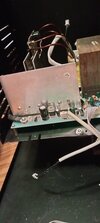
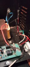
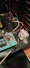
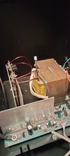
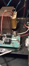
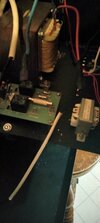
Where can I find information on this piece of equipment? I tried to get wiring diagram, replacement parts, power supply board, I searched the Internet, tried getting hold of the manufacturer but was not able to find out anything was able to download the owners manual is said it was 16 pages but after downloading there was 14 pages the last two #15 & #16 was blank nothing at all on them. The circuit board had one number and it match anything the cabinet has a serial ## on the front and on the sticker on the back it has a different serial number can't find any help info on this. All I need to know is on the board there is 3 places that are labeled T2-2/Start , T2-3/Charge , AC-L and there is a red and blue wire from the primary side of the big transformer they have 110v then there is a red wire from the small transformer that hooks to the common power cord wire they all have spade connectors and close tob each other where do the wires go I have been days try to get information on this can someone please help. I can post pictures of needed
 
No am not trying to fix a broken battery charger my friend took it to change the fuse that had blown and he had the thing for ever so I had to go pick it up and the wires was not hooked up and he took off with a someone other then his wife and no one has been able to contact him. So I am stuck with out my charger I hope the pictures help I am not the best person to take pictures I appreciate you taking the time to help me with this
 

Attachments

  • IMG20231227205511.jpg
    IMG20231227205511.jpg
    1.6 MB · Views: 75
  • IMG20231227205503.jpg
    IMG20231227205503.jpg
    1.5 MB · Views: 77
  • IMG20231227205454.jpg
    IMG20231227205454.jpg
    1.7 MB · Views: 78
  • IMG20231227205405.jpg
    IMG20231227205405.jpg
    1.8 MB · Views: 76
  • IMG20231227205350.jpg
    IMG20231227205350.jpg
    1.3 MB · Views: 71
  • IMG20231226221550.jpg
    IMG20231226221550.jpg
    1.3 MB · Views: 72
It looks like the AC power in cable is the white one?

The two transformer leads would presumably go to start and charge. If they are the right way around, Start should give a higher output voltage from the charger than the normal Charge setting.

It appears there is a socket for the lead from the small transformer in the middle of the board, just back from the two black relays? (just visible at the left of the last two photos).

It looks like the fuses may be soldered in? If so, they may be unchanged and that's why it is still in bits??
 

Latest threads

New Articles From Microcontroller Tips

Back
Top