Continue to Site

Welcome to our site!

Electro Tech is an online community (with over 170,000 members) who enjoy talking about and building electronic circuits, projects and gadgets. To participate you need to register. Registration is free. Click here to register now.

  • Welcome to our site! Electro Tech is an online community (with over 170,000 members) who enjoy talking about and building electronic circuits, projects and gadgets. To participate you need to register. Registration is free. Click here to register now.

Transformer winding, Which type is better?

Status
Not open for further replies.

polashd

Member
Dear all

I'm a hobbits. I'm going to re-wind a laminated EI core transformer.
I've to choose between two winding options.
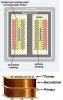
-First wind the primary(230v) on the bobbin, add lamination layer (lamination paper, etc), the wind the secondary(24-30v) on the lamination layer (like the top pic in the attachment).
-Using a partition on the bobbin to make separate sides for primary and secondary (like the bottom transformer in the attachment).

I want to know which is better and why?
Please suggest me.

rgds.
Didar
 

Attachments

  • transformer winding type.jpg
    transformer winding type.jpg
    55.1 KB · Views: 198
Hi,

There are a couple different ways to view this.

First, the layer on layer method provides the tightest coupling which means less leakage inductance. This provides for the least isolation safety however.

The side by side method is the best for isolation, and is actually required in order to pass a certain safety standard class that is good enough for humans to use in everyday life. There is some leakage inductance however, and that can be good because it helps filter the DC output if you intend to make a DC power supply out of it with rectifiers and capacitors. The output voltage will be reduced with load however.
 
Hi,
Little more questions- Ferrite transformers in SMPS are VERY smaller than iron. However these smaller has equal power like bigger iron core. Due to high frequency on ferrite? Or due to high inductance capacity of ferrite?

Another- why ferrite transformers need very high frequency? If we made ferrite core transformer for 50Hz mains or If we made iron core transformer for 50KHz SMPS then?
 
If we made ferrite core transformer for 50Hz mains or If we made iron core transformer for 50KHz SMPS then?
Iron cores get HOT at high frequencies.

A transformer is like a bucket to carry water in.
You can carry a very big iron bucket and walk slowly. You need work boots.
OR
You can carry a very small cup and run very fast and make many trips. You need running shoes.

In you example 50Hz and 50kHz is 1000:1 slow/faster.
In time, at 50kHz the voltage is across the transformer for 1/1000 as much time. The inductance is much lower, less turns at 50kHz.
 
Iron generally has higher inductance for a give core size than ferrites but it has much higher eddy-current loss at high frequencies as compared to a ferrite core.
Since the transformer inductance required is inversely proportional to frequency for a given magnetizing current, a ferrite core can be made much smaller, even allowing for the lower intrinsic magnetic permeability of the ferrite material, since it can operate at a much higher frequency,.
 
Didar Said "re-wind a "laminated" EI Core transformer.
So GUY's, It must be an Iron Core, 50 or 60 Hz Power Transformer.

My Opinion, Either Secondary Over Primary, Or Side By Side is OK.
If you have a Separated Bobbin for Side by Side, it gives better Isolation and is generally Easier to work with.

What is your Expected Output Voltage and Current?
 
Hi,
Little more questions- Ferrite transformers in SMPS are VERY smaller than iron. However these smaller has equal power like bigger iron core. Due to high frequency on ferrite? Or due to high inductance capacity of ferrite?

Another- why ferrite transformers need very high frequency? If we made ferrite core transformer for 50Hz mains or If we made iron core transformer for 50KHz SMPS then?

Hi,

The special grain oriented Si steel transformer laminations are made to have low loss and high permeability, typically 20000 Gauss, but even the thinnest laminations only work good up to maybe 400Hz for power applications and after that they start to show more loss which of course translates to lower efficiency.
The ferrites show less loss but tend to have less permeability, more typically 10 times less than steel, This means they work better at higher frequencies where less permeability is good enough to support a given primary voltage without saturation.

You can sort of think of a ferrite as being made out of a bunch of iron particles suspended in a non magnetic medium such as hardened epoxy resin. The resin keeps the particles apart from each other and thus lowers the tendency for electrical currents to flow in the core itself and this means higher efficiency. The separation distance between particles however (the epoxy in between) has the adverse effect of lowering the permeability because it acts like a distributed gap, and the introduction of any gap always reduces the permeability. So we get a lower permeability but less losses.
 
you should seperate 2 coil because heat release from coils not small. if wire wasn't wind well, quality of wire and core not high (such as poor core made from steel without silicon) your coils might overheat cause burn or hot wires have high resistance so it decrease transformer efficiency. if you wind the primary first then add layer layer then wind the secondary, your may have trouble if primary coli have a problem and need to replace.
my transformer used in lead battery charger wound primary coil first then the secondary. after short time, low quality diode broke down, DC current from battery passed through secondary coil made it generate heat to burn, the primary coil also "semi-burn" because heat from the primary. It spent me a lot of time to rewind my transformer.
BUT the first windind option make the transformer more efficiency (as MrAl said) than the second if cores and winds are good because less inductance leakage.
You can buy core like "C core" to improved efficiency. I saw this kind of coils in many Russian machines and power amplifiers. Very little hot and less hum release to the air.
 
What is your Expected Output Voltage and Current?

My expected output is 26vAC(rectified & filtered DC near 40vdc, I can't go higher as the schottky diode (1n5822) rectifier's reverse voltage limit is 40v. am I right?)
& current would be 2Amp (may be needed higher occasionally, I'll use it for banchtop hobby powersupply).

As the output V drops with load, would it be risky if AC output of the transformer is higher than 26v to get higher DC?

Didar
 
If your Primary Inductance Value is Correct for the Line Frequency and you use a 24 AWG for the Primary and a 16 AWG for the Secondary.
The Output Voltage should remain fairly Stable with 2 amps out.
 
Is this trans operating at mains frequencies, the fact you mentioned 1n5822 makes me think this might be a switcher.

If your new to winding transformers definately wind the pri and sec as seperate windings for safety.
 
Is this trans operating at mains frequencies, the fact you mentioned 1n5822 makes me think this might be a switcher.

The transformer will operate at mains frequency. 1n5822 x4 will be used as bridge rect and 1 as blocking diode.
If I can't go over 40vdc (because of 1n5822 (I don't have higher V rated Shottky)) I'll use LM2576 adj for the PSU.
 
No problem then. Keep the 2 windings apart.
 
My laminated EI core transformer core size is 25mm x 30mm, primary 230v, bobbin height 38mm (between top & bottom boarder, window width (from bobbin to core arm) 12mm, primary wire diameter 0.315mm(without insulation), secondary wire diameter 0.914mm
Q.
-what would be the turns/volt?
-How many watts I can expect?
-Space needed for primary?
-after winding primary how many turns (approx.) of secondary can be wind (or how many volts I can expect)?
-Output current?
 
Hi,

You have not specified the frequency nor the current, nor the secondary voltage required.

Just to start, assuming 50Hz and 10 percent max primary over voltage and laminations interleaved 1x1 and Bmax=20kG, you should use at least 5 turns per volt.
 
25 x 30mm, Sounds like a Pretty Small Transformer.
(Especially if it is for 230 volts and 50Hz.)
 
Hi,

That is what i assumed in post #15.
 
Based on the 5 Turns per Volt, If you wind 1150 Turns of 24 AWG for the Primary and 130 Turns of 16AWG for the Secondary, you should get 26 VAC out at 2 Amps.
Assuming you have Enough Space.

Don't Know Spacing of a Split Bobbin, So Using Secondary winding Over the Primary .

Based on 24 AWG (.53mm dia wire) with careful winding you should get about 56 turns in the 30mm Space
So it will require approximately 21 layers of wire, so that is an approximate 22mm in height.
Their Might Not be Enough room for the Secondary.

Hopefully I did this Correct
 
Status
Not open for further replies.

Latest threads

New Articles From Microcontroller Tips

Back
Top