Electro Tech is an online community (with over 170,000 members) who enjoy talking about and building electronic circuits, projects and gadgets. To participate you need to register. Registration is free. Click here to register now.
Welcome to our site! Electro Tech is an online community (with over 170,000 members) who enjoy talking about and building electronic circuits, projects and gadgets. To participate you need to register. Registration is free. Click here to register now.
There has to be enough signal at L2 to turn on Q2. If L2 has too many turns, the loading on L1 might kill the oscillator. Otherwise, the turns ratio is not critical. I think 1:1 or 2:1 would work. If it were me, I would put a coupling cap and resistor to ground on the base of Q2.
The resistor controls the drive level to Q2. If the resistor is too large, Q2 output will have a small signal. You would have to experiment to see what value is best. Driving Q2 hard into saturation would not be good.
The way it works, is the coupling cap charges up when the base-emitter conducts, so the next alternation only drives the base enough to compensate for the charge lost thru the resistor.
what am i missing here? you said that the larger the resistor, the smaller the output signal. isn't it the other way around? if the resistor is a small value, then wouldnt it ground the base of Q2, resulting in a smaller output? please shoot some holes in my theory so i can learn :lol:
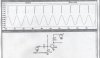
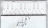
The output is smaller with a large base resistor because the coupling cap charges up, putting a negative bias on the base. With 1 meg base resistor in the simulation, the base voltage barely gets up to 0.8 volts; but when the base resistor is 10K, the cap discharges more and there is a larger slug of base current and larger output.
This site uses cookies to help personalise content, tailor your experience and to keep you logged in if you register.
By continuing to use this site, you are consenting to our use of cookies.