Continue to Site

Welcome to our site!

Electro Tech is an online community (with over 170,000 members) who enjoy talking about and building electronic circuits, projects and gadgets. To participate you need to register. Registration is free. Click here to register now.

  • Welcome to our site! Electro Tech is an online community (with over 170,000 members) who enjoy talking about and building electronic circuits, projects and gadgets. To participate you need to register. Registration is free. Click here to register now.

RFID 125kHz clock source

Status
Not open for further replies.

VictorPS

Member
I am modifying 125Khz RFID reader for Proximity card.

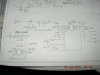
The original design of the reader circuit is quite simple, it use CMOS 4069 inverter IC to demodulated the signal to digital.
For the clock 125Khz, it is derived from 8Mhz crystal , and divide down to 125Khz by 74HC393 .

I have success decode the read data using 16F628A.
In order to save the crystal and 74HC393, I like to use 16F628A to generate the 125khz clock as well.
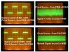
I use hardware PWM to generate 125khz, 50% duty , a nice square wave is generate at pin_b3.

However, when this PWM clock signal is feed to MIC4429 to drive antenna, the RFID detection range reduce by half, compare by using crystal divide clock source.
Also, there is more noice appear on 4069 when using the 16F628A PWM clock source.

Any special requirement for RFID clock? It shall be very straight forward as I think, but the two different clock source signal is given 2 different result.
They look almost identical under osciloscope. I have check grounding and other like decoupling cap, but not helping at all.

The 16F628 is using 4Mhz internal ocsilator. Will this be a problem?

Pls help, I am almost cracy about this problem.
Let me know if you need more info.

Thank you.
 

Attachments

  • RFID-Sch.JPG
    RFID-Sch.JPG
    150.9 KB · Views: 1,728
Last edited:
hi victor,
You could use the PIC osc out pin to drive a HC393 to give a 125KHz signal.
As you have a 4MHz PIC and crystal, use one less divider stage in the HC393.

Is it possible to scope the voltage levels and edges of the PWM output from the PIC pin, when the MIC4429 is connected? Let us know.
 
I am using Internal Oscilator of 16F628A, so not possible to use 74HC393.

The input signal on MIC4429 pin 2 is a nice square wave, I will try to put snapshot photo later.
 
VictorPS said:
I am using Internal Oscilator of 16F628A, so not possible to use 74HC393.

The input signal on MIC4429 pin 2 is a nice square wave, I will try to put snapshot photo later.
PICs with internal Osc usually have a clkout (OSC/4) RA6 pin settable with the config fuses. You would get 1MHz out with a 4MHz internal osc.

PS the 74HC393 is a ripple counter, jittery output is the norm. See if a synchronous counter might work instead like a 74HC191

Better yet use a 16F88 and set the internal clock to 500KHz (that will give you 125KHz on the CLKOUT pin)
 
Last edited:
Hmm, just on the RFID decoder, have you considered this?

**broken link removed**
  • * Fully-integrated, low-cost method of reading passive RFID transponder tags
  • * 2400 baud TTL serial interface (output only) to PC, BASIC Stamp module and other processors.
  • * Requires single +5VDC supply
  • * Bi-color LED for visual indication of activity
  • * 0.100. pin spacing for easy prototyping and integration
 
It's a nice $39 module, but it's read only and you'll learn very little about how RFID works. For an article read Elektor Sept 2006.
Betcha whatever processor they used on it isn't programmed in BASIC.
 
blueroomelectronics said:
PICs with internal Osc usually have a clkout (OSC/4) RA6 pin settable with the config fuses. You would get 1MHz out with a 4MHz internal osc.

PS the 74HC393 is a ripple counter, jittery output is the norm. See if a synchronous counter might work instead like a 74HC191

Better yet use a 16F88 and set the internal clock to 500KHz (that will give you 125KHz on the CLKOUT pin)
I will try to use clockout, but I hope I can save 74HC393, and learn more.
Everything is the same, I just change one variable that is clock source, but I get 2 different result.

I attached here the scope signal that measure on pin 2 of MIC4429 & pin2 of 4069.

Hope you guys can give me more hint.
 

Attachments

  • RFID-Clock.jpg
    RFID-Clock.jpg
    58.5 KB · Views: 791
blueroomelectronics said:
Did you put 0.1uf decoupling caps on all the ICs VDD & VSS. Didn't see them in the schematic.
Yes, I did try 0.1uf, 0.01uf, 4700uf on 4069 & MIC4429, but it does not help .
 
And most importantly the PIC... 0.1uf is generally the cap of choice.

Might want to look at the CD4060 with a 4MHz crystal. It's a ripple counter with an oscillator built in.
 
I have try RA6 pin 1MHz clockout on 16F628A, CLKIN to 74HC393, but it is same problem.

Seem like problem is from the PIC itself, not the PWM out or clock source issue. I shall focus on others issue.

Will the PIC radiate/emit any noise (magnetic?) to air ?

I suspect there is unwanted oscilation happend to the circuit, but could not found it.
 
Yes, I have 0.1uF on PIC. I configure NOMCLR for PIC, so no pull high require.

I notice if I have a 0.056uF cap parallel with antenna (CON1), the noise has much improve, but the detection range still 2inch , which normal shall be 4inch.
 
I am not sure if I am right, but I have a feeling, that the 125Khz must be very stable, if not it will create harmonic distortion in the antenna.
 
hi victor,
By added the capacitor to the antenna, you will degrade the signal edges, thats why the noise and range are affected.

This should give you a clue regarding the drive difference between the HC393 output and the PIC's drive to the MIC4429. Its suggesting the PIC drive and edges are slower than the 35MHz+ capability of the HC device.

As a test use an intermediate HC buffer between the PIC output and MIC4429, see what difference that makes.
 
ericgibbs said:
This should give you a clue regarding the drive difference between the HC393 output and the PIC's drive to the MIC4429. Its suggesting the PIC drive and edges are slower than the 35MHz+ capability of the HC device.

As a test use an intermediate HC buffer between the PIC output and MIC4429, see what difference that makes.
No, I have try RA6 pin 1MHz clockout on 16F628A, CLKIN to 74HC393, but it is same problem.

I am tired about this.
May be I will just use 74HC393 and crystal to generate the 125Khz, additional cost to the product, no choice.

Previously, I think I can save the two compnent, but seem like I am wrong.

May be the PWM signal is not rock stable, may be there is a little phase shift, or may be it is not exactly 50% duty, and hense causing problem, but I don't have equipement to test it out.


Btw, is the 125khz must be a 50.00% duty cycle? no idea....
 
Yes, it might work, but I think may be no advantage to use CD4060 with a 4MHz crystal, as my original goal is to save the crystal and 74HC393.

I rather chose 8Mhz crystal to PIC16F628A, and A6 clock out to HC393.

Thank you,
 
Status
Not open for further replies.

New Articles From Microcontroller Tips

Back
Top