Continue to Site

Welcome to our site!

Electro Tech is an online community (with over 170,000 members) who enjoy talking about and building electronic circuits, projects and gadgets. To participate you need to register. Registration is free. Click here to register now.

  • Welcome to our site! Electro Tech is an online community (with over 170,000 members) who enjoy talking about and building electronic circuits, projects and gadgets. To participate you need to register. Registration is free. Click here to register now.

reading a schematic

Status
Not open for further replies.

mike_ss

New Member
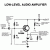
Hello, I am fairly new to this and have a couple of questions (that may be considered dumb to more advanced members) but If I don't ask I will never know. I am having a problem reading schematics. I can read the very simple ones but when capacators and such are in, I have problems. First of all, when there is a schematic is everything positive voltage except where a ground is marked? I posted this picture with a couple questions on how the circuit works. Can you please help me figure out how to read these. For example, look at R4. Positive voltage flows into the top, and then it goes directly to '-V'... how is this not a short circuit? I'm not asking for a four-year college description but just for some tips. Thanks, I appreciate it.
 

Attachments

  • r76_questions.gif
    r76_questions.gif
    12.4 KB · Views: 534
Would it help you if I told you that the electrons flow from - to +?

Follow your schematic starting from your ground, and you will have a different perpective on what all electronic components do.

Remember that there is a continuous loop from - to +.

Your resistor is not a short, as it restricts, therefore limits the flow of the electrons.
In series the current stays the same but the voltage drops.

You have to start visualizing this flow of electrons as water thru a pipe.

You'll get the hang of it.
 
Your first mistake is that the circuit uses a PNP transistor (and not an NPN). This means that the top part of the circuit is NEGATIVE and the bottom part (ground) is POSITIVE.

R4 would be easier to understand if it was drawn pointing upwards, rather than downwards, it seems designed to confuse?.

Electrolytic capacitors don't need to be connected to positive and ground (or in the case of this circuit negative and ground), they simply require a DC polarising voltage across them - in the case of C1 the negative end voltage is set by R1 and R2, the positive end needs to be connected to a point more positive (or less negative) than that.

In this circuit (because of the PNP transistor) EVERYTHING is negative with respect to ground - at one time this was EXTREMELY common (1960's ?) as most transistors were PNP).
 
Thanks a lot, what is the first sign that the whole circuit should be negative? Also when there is the capacitor like C1 since DC cannot 'flow' through capacitors where do you connect the two leads comming off of the capacitor. I think that is the biggest problem for me is, where to make the connections. Since you can't go in a straight line while reading the schematic. Thanks again for your help.
 
the two leads of the capacitor are connected to exactly what they're connected to in the schematic... the positive lead to ground, along with one lead each of R2 and R3, and the negative lead to the emitter of the transistor, and the other lead of R3. the same goes for all the other components... the schematic does literally show you where all the connections are made.

the sign that the whole circuit is negative is that the only supply voltage shown is "-V"... if the supply voltage is negative, then it is lower than ground, therefore ground would really be the positive rail.
 
the + labelled to the capacitor shows that the +ve pin of the capacitor is connected there.

and the ground symbol is actually +ve. Very uncommon for today's circuits.

If you want to do it another way, replace the PNP with the equivalent NPN and ground will be -ve, and the end of the 4.7K resistor will be +ve instead of -ve.
 
mstechca said:
the + labelled to the capacitor shows that the +ve pin of the capacitor is connected there.

and the ground symbol is actually +ve. Very uncommon for today's circuits.

If you want to do it another way, replace the PNP with the equivalent NPN and ground will be -ve, and the end of the 4.7K resistor will be +ve instead of -ve.
And swap ends with the capacitors.
 
Status
Not open for further replies.

Latest threads

New Articles From Microcontroller Tips

Back
Top