Hello,
New to the forum, and I hope I am posting in the correct location. Please advise if I've done something wrong....
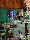
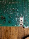
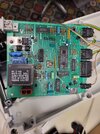
Trying to fix a Pfaff Model 1171 sewing machine for a friend. Mechanically the machine appears in great condition and well cared for. When powered up, the lights work, but the motor will not turn when the pedal is pressed. Feeding the motor directly, proves it spins and the wiring is in good condition, so I am assuming the problem is in the control circuit board. Very little information is available for this older model machine. The control circuit board is not available.
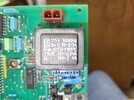
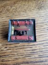
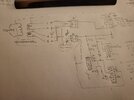
When checking the board, I see there is a small step down transformer with two secondaries. (See pictures.)
The label on the transformer says:
115 V 50/60 Hz,
12V 0.3VA
10V 2VA
Preliminary testing on the board shows the transformer outputs go to two AC to DC rectifier chips. (IC number B40C800DM) The AC voltage on one chip measures 18 volts and the second measures 0 volts. I removed the transformer from the circuit and tested it. With 120VAC applied to what I think are the primary pins the output voltages are as follows:
PINS 1-2 = 4.7V
1-4 = 13.5V
1-5 = 18.1V
2-4 = 2.7V
2-5 = 3.4V
4-5 = 6.2V
In circuit, PINS 1 and 5 feed one rectifier and appear OK at 18V. PINS 2 and 4 feed the second rectifier IC and show 0 volts when in circuit.
Questions:
- Do these transformer secondary voltages seem OK considering the rating is 10V and 12V?
- If there is a short on the board downstream of the rectifier chip, could this pull the AC voltage down to zero or would the IC isolate it?
Thank you for any help the the group can offer.
Dennis
New to the forum, and I hope I am posting in the correct location. Please advise if I've done something wrong....
Trying to fix a Pfaff Model 1171 sewing machine for a friend. Mechanically the machine appears in great condition and well cared for. When powered up, the lights work, but the motor will not turn when the pedal is pressed. Feeding the motor directly, proves it spins and the wiring is in good condition, so I am assuming the problem is in the control circuit board. Very little information is available for this older model machine. The control circuit board is not available.
When checking the board, I see there is a small step down transformer with two secondaries. (See pictures.)
The label on the transformer says:
115 V 50/60 Hz,
12V 0.3VA
10V 2VA
Preliminary testing on the board shows the transformer outputs go to two AC to DC rectifier chips. (IC number B40C800DM) The AC voltage on one chip measures 18 volts and the second measures 0 volts. I removed the transformer from the circuit and tested it. With 120VAC applied to what I think are the primary pins the output voltages are as follows:
PINS 1-2 = 4.7V
1-4 = 13.5V
1-5 = 18.1V
2-4 = 2.7V
2-5 = 3.4V
4-5 = 6.2V
In circuit, PINS 1 and 5 feed one rectifier and appear OK at 18V. PINS 2 and 4 feed the second rectifier IC and show 0 volts when in circuit.
Questions:
- Do these transformer secondary voltages seem OK considering the rating is 10V and 12V?
- If there is a short on the board downstream of the rectifier chip, could this pull the AC voltage down to zero or would the IC isolate it?
Thank you for any help the the group can offer.
Dennis