Continue to Site

Welcome to our site!

Electro Tech is an online community (with over 170,000 members) who enjoy talking about and building electronic circuits, projects and gadgets. To participate you need to register. Registration is free. Click here to register now.

  • Welcome to our site! Electro Tech is an online community (with over 170,000 members) who enjoy talking about and building electronic circuits, projects and gadgets. To participate you need to register. Registration is free. Click here to register now.

One Tube Code Practice Oscillator

Status
Not open for further replies.

Andy1845c

Active Member
Hey everyone.

I've been kinda absent from here for a while. (busy with other things:( )

But I am kicking around the idea of building this project.

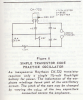
Dave's Homemade Code Practice Oscillator

I know a simple practice oscillator begs the use if a 555 IC or even a couple transistors, but I want to make this one as kind of a novelty.

It looks like a simple circuit, but I have never built anything with tubes before (half the reason for wanting to do this in the first place).

I happen to have 4 random tubes on hand. None happen to be the #43 tube that is used in the circuit on the link above.

I do have a pentode, but it appears to be a 6L6GC "Beam Power Pentode"

6L6GC - **broken link removed**

and here is the data sheet for the #43 tube **broken link removed**

Is there any chance I can sub the 6L6 in this application? Or is that just not going to work? I see the heater voltage and current are much different, but past that I just don't know enough about tubes to decide if i can make it work or if I should order a different tube.

Any help would be great :)

-Andy
 
It's a very basic blocking oscillator, and tube types here aren't critical. Just about any small signal type would work here. What other types do you have?
 
Two main problems:

1) The 6L6 ha a 6.3V filament..
2) The 6L6 plate is generally operated a lot higher than 30V.

If you provide a 6V filament supply and a B+ of at least 100V, it might work. You would need to have better enclosure, since 100V is a far cry from 30V.
 
Hey guys,

The other tubes I have.... one doesn't have a marking that I can find and the other 2 are not pentodes, ones a rectifier and the other was some kind of regulator tube.

My dad has a box of random tubes I am looking through now.... not seeing any #43's..... theres a couple #80 and #78 a 6D6, a 12SK7 (is this one a possibility? the datasheet is pretty vauge... I will search for a better one)..... and some that are not pentodes...... I take it i need a pentode for this? I have a #32, but thats a tetrode according that datasheet site.

The enclosure is not a problem, but looking at the circuit, I take it I would have 100v + across the code key, and thats not cool.

My local ham radio club has a homebrew program for the Feb. meeting and I wanted to make this old tube oscillator and a old fashioned straight key to go with it. So the voltage at the key needs to be a safe level.

EDIT - here is a better 12SK7 Datasheet - **broken link removed** problem is I don't know what exactly to look for on it as to minimum voltage ranges.
 
Last edited:
The 12SK7 would be the best candidate for that code practice oscillator project. It will work off 45V. You're not looking for linearity here, nor do you need lotsawatts either. I'd go with that one. You could power it with a 12V transformer to run the heater, and use a Walton Cockroft tripler for the DC rail.
 
Last edited:
Thanks Miles. I will see what I can come up with :)
 
I think a 50C5 or 6AQ5 would be a better choice than a 6L6 tube.

When I was in high school 40+ years ago I built a 1 tube code practice oscillator with a 50C5 tube. I think the circuit drawing was in the Amature Radio Handbook.

**broken link removed**

The 1966 RCA Receiving tube manual has a 1 tube code practice oscillator on page 25-7.

General Electric tube manual 1969 has a 2 tube code practice oscillator page 350.
 
Last edited:
Andy - I looked in my 1969 ARRL Handbook and see that the code practice oscillator is transistorized. I would bet that if you go back a few more years you'd find the vacuum tube version. As a rule, the circuit designs allowed for more common parts.

I will check with some of the local guys here to see if they have an older handbook with a vacuum tube code practice oscillator.
 
I think a 50C5 or 6AQ5 would be a better choice than a 6L6 tube.

When I was in high school 40+ years ago I built a 1 tube code practice oscillator with a 50C5 tube. I think the circuit drawing was in the Amature Radio Handbook.

A 50C5 (or any of its variants: 25C5, 17C5, 12C5, 6CU5) will definitely work. The 50C5 has an EEEEEEEEEEEEEEEEEEENORMOUS cathode for its power class (Pdmax= 5.5W -- still small signal territory). The heater power (50V @ 0.15A) is in the 20+ watt class. You might get useful output at 10V. a
After all, this type was made for operation at low voltages.

The 6AQ5 wouldn't be so good, and may not work at all, as this is a type intended for operation off a high voltage rail (250V -- 285V). It has a much smaller cathode and heater (6.3V @ 0.45A) and like a 6L6, probably won't work well at under 100V.
 
Neither my 1963 ARRL Handbook, nor my 1962 Radio Handbook have a tube CPO. By 1962, they have this circuit:
 

Attachments

  • CPO.png
    CPO.png
    300.9 KB · Views: 869
Last edited:
In my 1954 ARRL Handbook, there's a 6SN7 audio oscillator, but it's high impedance (4700 ohm) and isn't keyed. It uses 150 volts on the plates.
 
Neither my 1963 ARRL Handbook, nor my 1962 Radio Handbook have a tube CPO. By 1962, they have this circuit:
Good old leaky germanium transistors. No need for a bias resistor!
 
If you still want to pursue this project the following is a schematic from one of my tube manuals. I would not try to duplicate the circuit exactly but take a look at it.

**broken link removed**

Years ago there was no shortage of tubes designed to work off batteries. Good luck today finding any of them. The circuit above uses a pretty cool tube for its day. The 6BJ8 was a combination dual diode with a triode tossed in for good measure. You won't find one of those today easily but note how the triode is used in the circuit.

Overall T1 is just a transformer with 115 VAC primary and a 125 VAC secondary (@15 mA) and 6.3 VAC for the tube filament. C1 & C2 are 20 uF electrolytics rated at 150 VDC, R1 is a 1500 Ohm 1 Watt resistor. The configuration of the C1, C2 and R1 were very common years ago with R1 sometimes being a choke. R2 is a 100K .5 Watt pot. C3 is a .001 uF paper cap and C4 is a .03 uF paper cap (you won't find paper caps but any non electroylitic will do rated at 150 VDC or greater). Transformer T2 is a common audio output transformer of the day. The speaker taps were for matching various speaker impedance.

Notice where the key jack is in the circuit. We called this "cold cathode keying" as the key was at ground potential. Years ago I used an old Navy J38 key with open terminals. Keying on B+ wasn't a good idea.

Code Practice Oscillators like this were common and very forgiving in their construction. The triode would just about always oscillate. I suggest if you want to pursue this to find a triode and play around a little. Just be careful as unlike today's solid state low voltage circuits circuits like this can bite and I don't mean byte.

Ron
 
The circuit above uses a pretty cool tube for its day. The 6BJ8 was a combination dual diode with a triode tossed in for good measure. You won't find one of those today easily but note how the triode is used in the circuit.

What BS! I found 6BJ8s readily available at:

**broken link removed**

Vacuum Tubes.Net (Lowest Price Here)

SND Tube Sales

**broken link removed**

See Frank's for spec sheets, free to download.
 
OK, so I didn't overly look that hard. At least I contributed something. Sorry.

Ron
 
Back in 1951 I was in the Naval Reserve and built a code oscillator using a single 117L7 tube.
No transformers - just ran off of the mains.
Not the safest circuit around but it was cheap at that time and put out a great signal.
Too bad I never kept the schematic.
Pat - W9ZO
 
Looks like at least one of the suppliers referenced even has a #30. A little bit pricey, for nostalgia's sake.
 
Status
Not open for further replies.

Latest threads

New Articles From Microcontroller Tips

Back
Top