Continue to Site

Welcome to our site!

Electro Tech is an online community (with over 170,000 members) who enjoy talking about and building electronic circuits, projects and gadgets. To participate you need to register. Registration is free. Click here to register now.

  • Welcome to our site! Electro Tech is an online community (with over 170,000 members) who enjoy talking about and building electronic circuits, projects and gadgets. To participate you need to register. Registration is free. Click here to register now.

Newly registered here, but not new.....

Status
Not open for further replies.

tlewis38344

New Member
I been scouting around looking at PWM circuits and found this forum. Thought I would stop in and say hi to all........

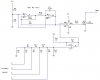
I drew up a binary controlled PWM circuit (attached). Before I build it, comments from any experts are needed and/or appreciated. I am rusty with my circuits. Been retired too long.

Thanks

USA Tom
 

Attachments

  • my pwm.JPG
    my pwm.JPG
    32.6 KB · Views: 139
I haven't calculated the PWM oscillator frequency, but it looks like the circuit will work as is. You'll want to add some bypass caps on the power supply leads and the junction of R8 & R9 for stability and noise suppression. The FET won't turn fully on with a 5V supply. Either use a logic level FET or a higher supply voltage. Welcome to the forums!
 
Last edited:
I haven't calculated the PWM oscillator frequency, but it looks like the circuit will work as is. You'll want to add some bypass caps on the power supply leads and the junction of R8 & R9 for stability and noise suppression. The FET won't turn fully on with a 5V supply. Either use a logic level FET or a higher supply voltage. Welcome to the forums!

Will do.

I am using this circuit to overcome the timing loop of the BS2 PIC. Using the PWM feature of the BS2 works, but gets you into real time problems especially in critical timing controls. I have several BS2s, so I am putting them back to work. They retired with me......
 
I'm not familiar with the Basic Stamp PICs, but ordinary PICs with hardware PWM require no software overhead once the PWM is setup and running. The software only has to update a register when the PWM duty cycle needs to be changed. If you need more speed and timing is critical, then programming in assembler on an ordinary PIC is the way to go. I do understand the appeal of raiding the junk box though. :)
 
I'm not familiar with the Basic Stamp PICs, but ordinary PICs with hardware PWM require no software overhead once the PWM is setup and running. The software only has to update a register when the PWM duty cycle needs to be changed. If you need more speed and timing is critical, then programming in assembler on an ordinary PIC is the way to go. I do understand the appeal of raiding the junk box though. :)


Junk box junkie........
I got cmos ICs date stamp 1980s...still works...wonder what the real shelf life is?

I'm building a line follower for my grandson. I kinda cheat for him.:)

Haven't written any code in many moons, but, it will come back if I can get over my "senior moments".
 
Last edited:
Status
Not open for further replies.

Latest threads

New Articles From Microcontroller Tips

Back
Top