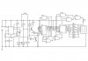
Hi all, I am working on a little circuit that it count from 1 (showing it when turned on) to 6 when button switch is pressed.
I have used an RC of 100K and 100n to give a PGT to Master reset, from 0 to 1.
Another RC of 10K and 10uF is used to give a PGT to the clock passing through a transistor Q1.
The signal from the switch pass through Q2, and the R15 is needed to limit the returning 0V from Q2 to Q1's emitter.
My doubt is: as I still don't have very strong knowledge about transistors, I am not sure this circuit will correctly work, however in the simulator seems all ok, but obviously I don't trust at all.
What do you think about it? I appreciate your suggestions.
Thank you for your interest.
Attachments
Last edited:
")
