Continue to Site

Welcome to our site!

Electro Tech is an online community (with over 170,000 members) who enjoy talking about and building electronic circuits, projects and gadgets. To participate you need to register. Registration is free. Click here to register now.

  • Welcome to our site! Electro Tech is an online community (with over 170,000 members) who enjoy talking about and building electronic circuits, projects and gadgets. To participate you need to register. Registration is free. Click here to register now.

LM317 Load Regulation problems...

Status
Not open for further replies.

adamthole

New Member
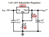
In one of my classes I made an power supply using an LM317. Everything works fine with it, except the load regulation is terrible, around 6% or so. One thing extra that I added to it is a PIC voltmeter. In order to do this I have 11K ohms across the load at all times. Could that 11K parallel resistance have anything to do with my terrible load regulation, or is it something else?

Thanks
 
why would you have a resistor across the load for a voltmeter?

I can understand a resistor (shunt) in series with the load for an ammeter

it has been my experience with the lm317, the decoupling and filter caps are not optional - make sure you have the datasheet recommended values on the input and the output.
 
Post your circuit. Maybe you used voltage-determining resistors for a premium LM117 instead of lower value ones for an LM317. If the resistors have a value too high then the unloaded output voltage is too high.

Didn't you use a pcb? A breadboard makes a mess of variable voltage regulators.

The datasheet explains how certain wiring can ruin voltage regulation.
On mine, I connected the voltage-setting resistors to its pins, and take the output from the heatsink tab. It has perfect regulation.
 

Attachments

  • lm317_600.png
    lm317_600.png
    10.3 KB · Views: 1,172
Alright, here is the PCB layout.

C1 is 4700uF Electrolytic Capacitor
C2 is a 0.1 uF ceramic capacitor
C3 is a 10uF tantalum capacitor
C4 is a 1uF tantalum capacitor
C5 is a 100uF electrolytic capacitor

VR1 is a 7805
VR2 is an LM317T (with big heatsink behind it)

IC1 is the PIC
TS1 is a temperature sensor
RF1 is a 2.5 V precision voltage reference
Vo is a 10K potentiometer, for adjusting the LCD contrast.

The external potentiometer (connected at POT and REF) is 5K
R1 is 240 ohm. It is also not located at the spot on the PCB anymore. I took it out of their and drilled new holes closer to the voltage regulator, after reading the part in the data sheet over load regulation. While I originally thought it fixed the problem, it came back later. Perhaps the connection just got worse? Does anyone see anything else wrong?
 

Attachments

  • pcb_911.jpg
    pcb_911.jpg
    130.6 KB · Views: 1,056
adamthole said:
Alright, here is the PCB layout.

C1 is 4700uF Electrolytic Capacitor
C2 is a 0.1 uF ceramic capacitor
C3 is a 10uF tantalum capacitor
C4 is a 1uF tantalum capacitor
C5 is a 100uF electrolytic capacitor

VR1 is a 7805
VR2 is an LM317T (with big heatsink behind it)

IC1 is the PIC
TS1 is a temperature sensor
RF1 is a 2.5 V precision voltage reference
Vo is a 10K potentiometer, for adjusting the LCD contrast.

The external potentiometer (connected at POT and REF) is 5K
R1 is 240 ohm. It is also not located at the spot on the PCB anymore. I took it out of their and drilled new holes closer to the voltage regulator, after reading the part in the data sheet over load regulation. While I originally thought it fixed the problem, it came back later. Perhaps the connection just got worse? Does anyone see anything else wrong?

I would have layed out the tracks to the big cap/ rectifier/regulator differently. In your case the regulator input track carries the pulsating currents to the capacitor. Preferred sequence is:
Rectifier > capacitor > regulator.

Also, the ground track could have been made much wider, ditto the positive track.

Klaus
 
You had the classic "poor regulation" layout where load current flowed through the same pcb trace as the reference resistor.
The layout has the same problem for the pot's ground connection, the load's current flows through the same skinny trace back to the filter cap and rectifier, dynamically changing the setting of the pot.

Your R1 and pot values are for the premium LM117 so the output voltage might be high without much load.

The LM317 is guaranteed to regulate well if its input voltage is 3V more than its output voltage, on the troughs of the input supply ripple.
Its "dropout" voltage is about 2V but it is far from regulating well at the input dropout voltage since it has already dropped-out.

The LM317 reduces its max output current (guaranteed at least 1.5A when cold) if the voltage across it exceeds 15V. With 40V across it, it is guaranteed to pass only 150mA. It also reduces its max output current when hot.
 
You say premium LM117. Is that a better version of the 317? Should I use that when I make a new board? I will update my circuit board, and post it here soon for comments.

I have posted what I have now. I still plan on making alot of the traces wider. See anything that I should bring my attention to, besides widening the traces?
 

Attachments

  • pcb_117.jpg
    pcb_117.jpg
    92.1 KB · Views: 733
The "premium" LM117 is much more expensive and has a max operating current half that of an LM317, therefore the values of the voltage-determining resistors for an LM317 should be halved.
The operating current flows to the output and if the resistors have a value too high then the output voltage rises without a load.

On your revised layout, the LM317 still gets powered by the fluctuating rectifier, instead of directly from the filter cap. There are huge current pulses between the rectifier and filter cap that causes huge fluctuations in voltage along the narrow path. Use thick traces between the rectifier and the main filter cap and connect everything directly to the main filter cap.

The pot is still connected to the 0V return from the load. It should be connected directly to the negative terminal of the main filter cap.

The traces from the LM317 to the output and the negative connection of the main filter cap to the 0V terminals are far too narrow for good regulation.
 
Status
Not open for further replies.

Latest threads

New Articles From Microcontroller Tips

Back
Top